Model HC2S3 Temperature and Relative Humidity Probe
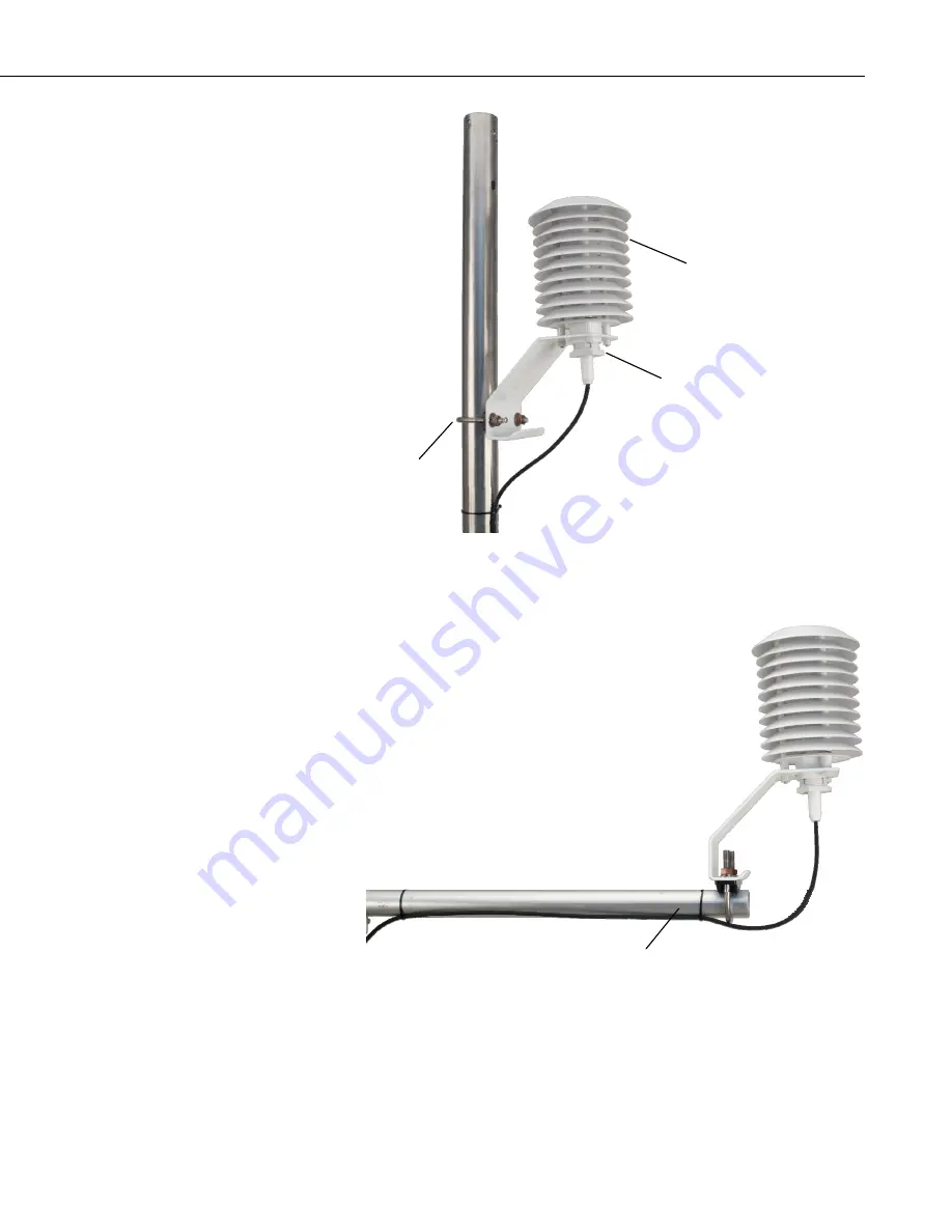
FIGURE 4-1. HC2S3 and 41003-5 Radiation Shield on a tripod mast
FIGURE 4-2. HC2S3 and 41003-5 Radiation Shield on a CM200 Series
Crossarm
41003-5
PN 27731 Hex Plug
U-bolt
CM200 Series Crossarm
3
Page 1: ...HC2S3 Temperature and Relative Humidity Probe Revision 10 12 C o p y r i g h t 1 9 9 0 2 0 1 2 C a m p b e l l S c i e n t i f i c I n c ...
Page 2: ......
Page 3: ...removing reinstalling and shipping defective products to Campbell Campbell will return such products by surface carrier prepaid within the continental United States of America To all other locations Campbell will return such products best way CIP Port of Entry INCOTERM 2010 prepaid This warranty shall not apply to any products which have been subjected to modification misuse neglect improper servi...
Page 4: ...ng container Campbell Scientific s shipping address is CAMPBELL SCIENTIFIC INC RMA _____ 815 West 1800 North Logan Utah 84321 1784 For all returns the customer must fill out a Statement of Product Cleanliness and Decontamination form and comply with the requirements specified in it The form is available from our web site at www campbellsci com repair A completed form must be either emailed to repa...
Page 5: ...Program Datalogger and Generate Wiring Diagram 4 5 Overview 7 6 Specifications 8 6 1 Temperature Sensor 9 6 2 Relative Humidity Sensor 10 6 3 Default Settings and Digital Interface 10 7 Installation 11 7 1 Siting 11 7 2 Assembly and Mounting 11 7 3 Wiring 11 7 4 Programming 13 7 4 1 Example Programs using Single Ended Measurement Instructions 14 7 4 2 Example Programs using Differential Measuremen...
Page 6: ... Protocol C 1 C 3 RS 485 Communications using an MD485 RS 485 Interface C 3 C 4 RS 485 Communications using an SDM SIO1 Serial I O Module C 5 Figures 4 1 HC2S3 and 41003 5 Radiation Shield on a tripod mast 3 4 2 HC2S3 and 41003 5 Radiation Shield on a CM200 Series Crossarm 3 Tables 5 1 Recommended Lead Lengths 7 7 1 Connections for Single Ended Measurements 12 7 2 Connections for Differential Meas...
Page 7: ...ed as a precision scientific instrument Do not touch the sensor element The black outer jacket of the cable is Santoprene rubber This compound was chosen for its resistance to temperature extremes moisture and UV degradation However this jacket will support combustion in air It is rated as slow burning when tested according to U L 94 H B and will pass FMVSS302 Local fire codes may preclude its use...
Page 8: ...de of the 41003 5 base 2 Attach the radiation shield to the tripod mast crossarm or tower leg using the supplied U bolt See FIGURE 4 1 and FIGURE 4 2 for examples of shield mounting 3 Insert the probe into the radiation shield leaving about 2 5 cm 1 in exposed below the hex plug 4 Tighten the hex plug such that it compresses against the body of the HC2S3 to hold it inside the radiation shield 5 At...
Page 9: ...re and Relative Humidity Probe FIGURE 4 1 HC2S3 and 41003 5 Radiation Shield on a tripod mast FIGURE 4 2 HC2S3 and 41003 5 Radiation Shield on a CM200 Series Crossarm 41003 5 PN 27731 Hex Plug U bolt CM200 Series Crossarm 3 ...
Page 10: ...rt Cut to Program Datalogger and Generate Wiring Diagram The simplest method for programming the datalogger to measure the HC2S3 is to use Campbell Scientific s SCWin Short Cut Program Generator 1 Open Short Cut and click on New Program 2 Select a datalogger and scan interval 4 ...
Page 11: ...stant power or panel switched power uses less current then click the right arrow to add it to the list of sensors to be measured 4 Define the name of the public variables Variables default to AirTC and RH that hold the air temperature and relative humidity measurements Select the desired units of measure Units default to Deg C 5 ...
Page 12: ...Model HC2S3 Temperature and Relative Humidity Probe 5 Choose the outputs for the AirTC and RH and then select finish 6 Wire according to the wiring diagram generated by SCWin Short Cut 6 ...
Page 13: ...ay Switching power avoids the constant current flow through datalogger ground which can affect the accuracy of low level single ended voltage measurements primarily with older dataloggers such as the 21X Probes are polarity protected by the keyed connector and a diode in the connector interface provided with the Campbell Scientific cable Campbell Scientific offers two filters Polyethylene filter D...
Page 14: ...mote Automated Weather Station cable termination option RQ The HC2S3 QD is included with the RAWS F Quick Deployment Remote Automated Weather Station and can be ordered as a replacement part Its cable has a 65 in length and terminates in a military style connector that attaches to the Temp RH connector on the RAWS F connector panel 6 Specifications Features Well suited for long term unattended app...
Page 15: ...V power 3 m 10 ft with 5 V power Analog outputs Offset at 0 V 3 mV maximum Deviation from Digital Signal 1 mV 0 1 C 0 1 RH 6 1 Temperature Sensor Sensor PT100 RTD IEC 751 1 3 Class B with calibrated signal conditioning Temperature Measurement Range 50 to 100 C default 40 to 60 C Temperature Output Signal Range 0 to 1 0 V Accuracy at 23 C 0 1 C with standard configuration settings Long Term Stabili...
Page 16: ... 80 RH step change 1 m s air flow at sensor 22 s with PE filter 30 s with Teflon filter RH Accuracy over Temperature The black outer jacket of the cable is Santoprene rubber This compound was chosen for its resistance to temperature extremes moisture and UV degradation However this jacket will support combustion in air It is rated as slow burning when tested according to U L 94 H B and will pass F...
Page 17: ...is used to mount the probe inside the 41003 5 Radiation Shield as described in Section 4 Quickstart Attach the probe to the cable by aligning the keyed connectors pushing the connectors together and tightening the knurled ring When exposed to solar radiation the probe must be housed in a radiation shield such as the 41003 5 naturally aspirated shield or the 43502 motor aspiration shield please ref...
Page 18: ...cted to AG on the CR10 X and CR500 CR510 or to on the CR1000 CR5000 and CR23X Doing otherwise will connect the datalogger s analog and power ground planes to each other which in some cases can cause offsets on low level analog measurements To avoid 2 mA flowing into analog ground switch power on off for its measurement CAUTION TABLE 7 1 Connections for Single Ended Measurements Color Description C...
Page 19: ...nnecting the probe to a prewired enclosure RAWS P station RAWS F station or CWS900 Wireless Sensor Interface Our prewired enclosures RAWS P stations and RAWS F stations include a datalogger program Refer to the Wireless Sensor Manual for programming information if using the probe with a CWS900 NOTE The temperature and relative humidity signals from the HC2S3 are measured using either single ended ...
Page 20: ...uctions The example programs for the CR1000 and CR10X use the SW12V terminal to switch power to the probe delay for 3 seconds and measure the output voltages using single ended measurement instructions Relative humidity and temperature deg C are measured on single ended input channels 1 and 2 respectively The program sets relative humidity equal to 100 if the measured value is greater than 100 but...
Page 21: ...TC 1 mV2500 2 0 0 _60Hz 0 1 40 PortSet 9 0 Turn off switched 12V If RH 100 AND RH 103 Then RH 100 CallTable Table1 NextScan EndProg CR10 X program using single ended measurement instructions CR10X program to measure HC2S3 with single ended inputs Table 1 Program 01 5 0000 Execution Interval seconds 1 Do P86 Turn on switched 12V 1 41 Set Port 1 High Jumper from C1 to SW 12V CTRL 2 Excitation with D...
Page 22: ...0 Then Do 7 If X F P89 1 1 X Loc RH 2 4 3 103 F 4 30 Then Do 8 Z F x 10 n P30 1 100 F 2 0 n Exponent of 10 3 1 Z Loc RH 9 End P95 10 End P95 11 If time is P92 1 0 Minutes Seconds into a 2 60 Interval same units as above 3 10 Set Output Flag High Flag 0 12 Set Active Storage Area P80 1 1 Final Storage Area 1 2 101 Array ID 13 Real Time P77 1 1220 Year Day Hour Minute midnight 2400 14 Average P71 1 ...
Page 23: ... 0 60 Min 10 Average 1 Battery_volts FP2 FALSE Average 1 Ptemp FP2 FALSE Average 1 AirTC FP2 FALSE Sample 1 RH FP2 EndTable BeginProg Scan 1 Sec 1 0 Run main scan 1 second Battery Battery_volts PanelTemp Ptemp_C 250 add additional instructions to be executed every 1 second CallTable Table1 NextScan SlowSequence Scan 5 Sec 0 0 Run slow sequence scan every 5 seconds PortSet 9 TRUE Turn on HC2S3 Dela...
Page 24: ... RH DataTable Temp_RH True 1 DataInterval 0 60 Min 0 Average 1 AirTC IEEE4 0 Sample 1 RH IEEE4 EndTable BeginProg Scan 1 Sec 1 0 HC2S3 Temperature Relative Humidity Sensor measurements AirTC and RH VoltDiff AirTC 1 mV2500 1 True 0 _60Hz 0 1 40 VoltDiff RH 1 mV2500 2 True 0 _60Hz 0 1 0 If RH 100 And RH 103 Then RH 100 CallTable Temp_RH NextScan EndProg CR10 X program using differential measurement ...
Page 25: ...time is P92 1 0 Minutes Seconds into a 2 60 Interval same units as above 3 10 Set Output Flag High Flag 0 9 Set Active Storage Area P80 1 1 Final Storage Area 1 2 101 Array ID 10 Real Time P77 1 1220 Year Day Hour Minute midnight 2400 11 Average P71 1 1 Reps 2 3 Loc AirTC 12 Sample P70 1 1 Reps 2 4 Loc RH 7 5 Measuring Probes with Long Cables For cable lengths longer than 6 1 m 20 ft Campbell Scie...
Page 26: ... C When there are not enough inputs available on the datalogger to allow for differential measurements single ended measurements can be made and the errors associated with cable length subtracted as offsets 8 Sensor Maintenance Corroded discolored or clogged filters should be replaced To replace the filter unscrew the filter from the probe and pull it straight away being careful not to bend or dam...
Page 27: ...g is disabled for probes purchased through Campbell Scientific Accuracy of the humidity measurement over temperature is shown in the graph in Section 6 2 For example at 20 C the accuracy is 2 3 so a reading of 102 3 at 100 humidity is within the accuracy specification Programs created by Short Cut set humidity values greater than 100 and less than 103 to 100 Humidity values greater than 103 are le...
Page 28: ... Nonfederal Automated Weather Stations and Networks in the United States and Canada A Preliminary Survey Bulletin Am Meteor Soc 73 No 4 449 457 Weiss A 1977 Algorithms for the calculation of moist air properties on a hand calculator Amer Soc Ag Eng 20 1133 1136 WMO 2008 Guide to Meteorological Instruments and Methods of Observation World Meteorological Organization No 8 7th edition Geneva Switzerl...
Page 29: ...por pressure It follows then from Eq A 1 that a change in air temperature will change the relative humidity without causing a change absolute humidity For example for an air temperature of 20 C and a vapor pressure of 1 17 kPa the saturation vapor pressure is 2 34 kPa and the relative humidity is 50 If the air temperature is increased by 5 C and no moisture is added or removed from the air the sat...
Page 30: ...ation Vapor Pressure SatVP e_Sat AirTC Compute Vapor Pressure RH must be a fraction e_kPa e_Sat RH_Frac CallTable Temp_RH NextScan EndProg A 1 Measurement Below 0 C The HC2S3 provides a humidity reading that is referenced to the saturated water vapor pressure above liquid water even at temperatures below 0 C where ice might form This is the common way to express relative humidity and is as defined...
Page 31: ... 2 parameter scale and unit Temperature 40 60 deg C Communications Protocol RO ASCII RS 485 Address 0 Device name Probe type Humidity temperature adjustment Device write protection Disabled Limit humidity output to 100 RH Disabled Out of limit value digital alarm Disabled Data recording Enabled loop mode 10 min interval Automatic humidity sensor test Disabled Humidity sensor drift compensation Dis...
Page 32: ...river must be installed on the PC Both the driver and the installation instructions document E M HW4v3 Main are located on the HW4 CD IMPORTANT B 3 Changing the Temperature Range Install the HW4 software and drivers for the AC3001 USB cable on the PC Connect the HC2S3 probe to the AC3001 cable making sure the connectors are properly aligned before tightening the knurled ring Plug the AC3001 cable ...
Page 33: ...mV for the temperature range If the range has been changed from the default 40 to 60 then the multiplier and offset for the measurement instruction will have to be changed from those shown for the program examples in Section 7 4 For example for a range of 60 to 30 the multiplier to convert the measurement result mV to temperature is the full scale range of temperature divided by the full scale ran...
Page 34: ...s for CR1000 datalogger with the sensor wired to SE channel 2 Public AirTC VoltSe AirTC 1 mV2500 2 0 0 _60Hz 0 09 60 Example measurement instruction for CR10X datalogger 1 Volt SE P1 1 1 Reps 2 5 2500 mV Slow Range 3 2 SE Channel 4 1 Loc AirTC 5 0 09 Multiplier 6 60 0 Offset ...
Page 35: ...Interface Type UART Universal Asynchronous Receiver Transmitter Organization Dialog duplex Default Configuration Baud rate 19200 Parity none Data bits 8 Stop fits 1 Flow Control none Logical Levels Logical 0 0 3V VDD Logical 1 0 8V VDD C 2 HC2S3 Communications Protocol Complete information on the HC2S3 Commands and Communication Protocol can be found in the Rotronic E M AC3000 CP_XX manual availab...
Page 36: ...ring unit 0 1 Bool Temperature alarm out of limits Char Temperature trend or Dp String Calculated parameter type nc no calculation Dp dew point Fp frost point 1234 56 Float Calculated numerical value C String Calculated parameter engineering unit 0 1 Bool Calculated parameter alarm out of limits Char Calculated parameter trend or 1 255 Byte Device type HygroClip Logger HF HM V1 0 String Firmware v...
Page 37: ...described below Settings for the RS485 port on the MD485 must be configured to match the configuration of the HC2S3 which are 19200 baud No Parity 8 Data Bits 1 Stop bit and No Flow Control Device Configuration Utility CSI software available as a free download is used to configure the MD485 Configuration settings for the MD485 are shown below MD485 Tab CS I O AND RS 485 CS I O Tab SDC Address 7 RS...
Page 38: ... probe Example CR1000 Program CR1000 Program Declare variables Public SerialIndest As String 100 Dim String_1 As String Const CRLF CHR 13 CHR 10 Dim HC2S3_Split 17 As String 40 Alias HC2S3_Split 2 RH_Str RH string Alias HC2S3_Split 6 TempC_Str Temp string Alias HC2S3_Split 17 HC2S3_SN_Str HC2S3 serial number string Public TempC RH NBytesReturned DataTable Table1 1 1 DataInterval 0 15 Min 10 Averag...
Page 39: ...ex COMport 32 at 19200 baud no parity 1 stop bit and 8 data bits and serial instructions to send the RDD command to get temperature and relative humidity data from the probe Sensor Wiring E2 05XX MOD Cable SDM SIO1 CR1000 Blue Z Red Y Gray Yellow G Green 12V Clear Ground SDM SIO1 Wiring SDM SIO1 CR1000 C1 C1 C2 C2 C3 C3 G G 12V 12V If the Rotronic cable includes brown and white wires voltage signa...
Page 40: ...nsorPort 32 SDM SIO1 rotary switch set at 0 DataTable Table1 1 1 DataInterval 0 15 Min 10 Average 1 TempC FP2 False Sample 1 RH FP2 EndTable BeginProg SerialOpen SensorPort 19200 51 100 200 51 is for half duplex String_1 F00RDD CRLF RS485 command to send data Scan 5 Sec 0 0 SerialFlush SensorPort SerialOut SensorPort String_1 0 1 100 Send command to send data Delay 0 500 mSec Get data from probe S...
Page 41: ......
Page 42: ...entific Canada Corp CSC 11564 149th Street NW Edmonton Alberta T5M 1W7 CANADA www campbellsci ca dataloggers campbellsci ca Campbell Scientific Centro Caribe S A CSCC 300 N Cementerio Edificio Breller Santo Domingo Heredia 40305 COSTA RICA www campbellsci cc info campbellsci cc Campbell Scientific Ltd CSL Campbell Park 80 Hathern Road Shepshed Loughborough LE12 9GX UNITED KINGDOM www campbellsci c...