User Guide
3
The ringer equivalence number (REN) of the DCSCOM is 3. For
correct operation you should ensure that the sum of the RENs for
all equipment connected to one telephone line does not exceed 4.
You can usually assume that British Telecom equipment has a REN
of 1 unless otherwise marked.
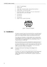
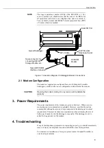
Figure 2 Schematic Diagram of Datalogger-Modem Connections
2.1 Modem Configuration
The modem is supplied pre-configured for use with Campbell Scientific
dataloggers, and there are no user configurable switches inside the modem.
Opening the modem casing for any reason will invalidate the
warranty.
3. Power Requirements
The power requirements of the modem are given in Section 1. When not com-
municating, power consumption is negligible. However, note that the on-line
consumption, although not great, is large compared to the datalogger’s normal
requirements. This must be taken into consideration when estimating the size of
battery pack needed to run the datalogger, especially if the datalogger is to be
called for long periods via the modem.
4. Troubleshooting
If any of the telephone equipment is not operating properly, you should immediately
remove it from your telephone line and establish the cause of the problem.
For assistance in installation or for repair, please contact Campbell Scientific or
your local representative.
NOTE
CAUTION
To BT Modular
Telephone Socket
DCSCOM
Modem
Special DCSCOM
Interface Connector
SC12 Cable
Typical Datalogger
Spare connector for
connecting SM192
Storage Module, etc.
Serial I/O Port
Summary of Contents for DCSCOM
Page 1: ...DCSCOM Telephone Modem User Guide Issued 1 3 99 Copyright 1999 Campbell Scientific Ltd...
Page 2: ......
Page 4: ......
Page 6: ......
Page 10: ......


