background image

Wireless Sensor Network 

up whenever a measurement is taken and the red LED will light up 
whenever the measurements are transmitted to the base station. 

6.


Connect the battery pack to the next wireless sensor, press in the Setup 
button for 8-10 seconds, and wait for that sensor to pair with the base 
station radio.  It is also possible to power all the sensors at the same time, 
press the button to start the linking, and wait for them to autodiscover the 
base station.  

7.


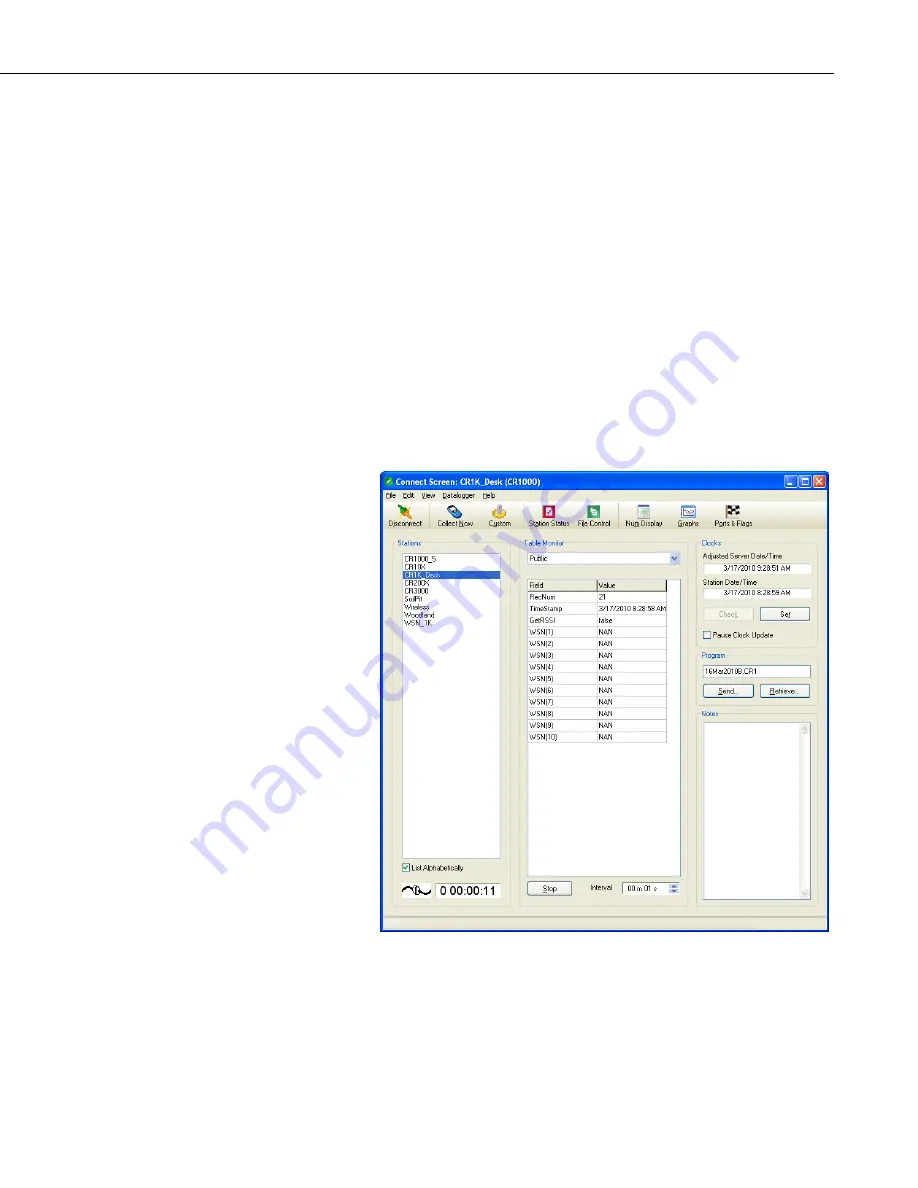
To verify that all sensors have been discovered, you can view real-time 
data from the sensors from LoggerNet’s Connect screen.  There are two 
ways to do this.  First, from the Table Monitor area of the Connect screen, 
choose Public from the drop down menu.  Then click the Start button at 
the center bottom of the Connect screen.  Prior to sensor discovery, the 
numeric monitor will display the name of the public variable specified in 
the CWB100 instruction with NAN as the output (if no configuration 
string is specified).  Once any sensor has been discovered, the Public table 
will disappear and must be selected again from the drop down menu.  At 
that time the newly discovered sensor names will appear in the Public 
table.  On the next datalogger scan, the sensor values will also appear. 


8.


The second way to view real-time data from the sensors is to select the 
Num Display button at the top of LoggerNet’s Connect screen and choose 
Display 1, Display 2, or Display 3.  When the Numeric Display window 
opens, click the Add button.  When the Add Selection window appears, 
select Public to highlight it and then drag it to a gray space in the Numeric 
Display window.  This will populate the window with names of variables 
in the Public Table.  Click the Start button to begin monitoring. 

39 

Summary of Contents for CWB100

Page 1: ...Wireless Sensor Network Revision 9 11 C o p y r i g h t 2 0 1 0 2 0 1 1 C a m p b e l l S c i e n t i f i c I n c ...

Page 2: ......

Page 3: ...return such products by surface carrier prepaid within the continental United States of America To all other locations Campbell will return such products best way CIP Port of Entry INCOTERM 2010 prepaid This warranty shall not apply to any Campbell products which have been subjected to modification misuse neglect improper service accidents of nature or shipping damage This warranty is in lieu of a...

Page 4: ...ng container Campbell Scientific s shipping address is CAMPBELL SCIENTIFIC INC RMA _____ 815 West 1800 North Logan Utah 84321 1784 For all returns the customer must fill out a Statement of Product Cleanliness and Decontamination form and comply with the requirements specified in it The form is available from our web site at www campbellsci com repair A completed form must be either emailed to repa...

Page 5: ...cifications 10 2 2 2 CWB100 Electrical Specifications 10 2 2 3 CWB100 Environmental Specifications 11 2 2 4 Datalogger Compatibility 11 2 3 CWS220 Specifications 11 2 3 1 CWS220 Physical Specifications 11 2 3 2 CWS220 Electrical Specifications 12 2 3 3 CWS220 Environmental Specifications 12 2 4 CWS655 Specifications 12 2 4 1 CWS655 Physical Specifications 12 2 4 2 CWS655 Electrical Specifications ...

Page 6: ... Verify that Data is being Transmitted 28 3 9 Physical Connections 28 3 9 1 Connecting the Base Station to the Datalogger 28 3 9 2 Connecting Sensors to the CWS900 29 4 Programming the Datalogger 29 4 1 Array Declaration 29 4 2 CWB100 Instruction 30 4 2 1 Configuration String 31 4 2 2 Field Names 32 4 2 3 Status Monitoring 32 4 3 ArrayIndex Instruction 33 4 4 CWB100RSSI Instruction 34 4 5 CWB100Ro...

Page 7: ...es 1 2 1 CWB100 Wireless Base Station 2 1 3 1 CWS220 Wireless Infrared Radiometer 3 1 4 1 CWS655 Wireless Water Content Reflectometer 4 1 5 1 CWS900 Wireless Sensor Interface 5 3 1 1 A205 CWS to PC Interface 15 3 1 2 Connection of A205 15 3 9 1 CWB100 Wiring Connections 28 3 9 2 CWS900 Connector Pin Out 29 B 3 1 Input Sample Vectors B 4 B 3 2 Mean Wind Vector B 5 B 3 3 Standard Deviation of Direct...

Page 8: ...Wireless Sensor Network Table of Contents iv ...

Page 9: ...hich serves as the gateway to the network Although compatible dataloggers use the PakBus communication protocol PakBus is not used for the datalogger to base station communication nor for the base station to sensor communication In other words the CWB100 and wireless sensors are not PakBus devices The base station communicates with all of the wireless sensors in the network Any sensor can serve as...

Page 10: ...sors do not initiate any communication except during Network Discovery Instead they transmit only when polled by the base station 1 2 CWB100 Wireless Base Station The CWB100 is the master radio in the wireless sensor network and serves as the interface between the datalogger and the wireless sensors It holds information for the routes to all the sensors in the network and is responsible for pollin...

Page 11: ...y surface of interest Because the CWS220 is wireless it can be mounted in many locations that would be problematic for a cabled sensor The CSW220 includes a thermopile for measuring a millivolt output dependent on the target to sensor body temperature difference A thermistor measures the temperature of the sensor body The sensor body temperature is used to reference the target temperature The cali...

Page 12: ...g volumetric water content of the surrounding media hence the name water content reflectometer The electrical conductivity of the surrounding medium is derived from signal attenuation information This is accomplished by exciting the rods with a known non polarizing waveform and determining the signal attenuation due to EC The EC measurement is used to correct the oscillator period and is also avai...

Page 13: ...s or making bridge measurements It has a sealed connector for use with a variety of sensors such as temperature humidity probes rain gages wind monitors or other low power sensors The type of measurement that the sensor performs is configured using Wireless Sensor Planner Network Planner or DevConfig software FIGURE 1 5 1 CWS900 Wireless Sensor Interface The CWS900 outputs 4 12 values depending on...

Page 14: ... Temperature C Probe Pressure kPa Relative Humidity Leaf Wetness Sensor V Dissolved Oxygen V pH V Signal Strength Battery Voltage V CWS900 Internal Temperature C Single Ended Channel 1 Measurement Single Ended Channel 1 and 2 Measurement Single Ended Channel 1 2 and 3 Measurement Differential Channel Measurement Switch Closure Pulse Count Low Level AC Rain Gage Pyranometer or Quantum Sensor 109 Te...

Page 15: ...gorithm deg Resultant Mean Wind Speed m s Resultant Wind Dir Avg deg Resultant Wind Dir Std Dev CSI algorithm deg Signal Strength Battery Voltage V CWS900 Internal Temperature C 05103 05103 45 or 05106 RM Young Wind Monitor 05305 RM Young Wind Monitor 03002 RM Young Wind Sentry Set 034B Met One Windset 40C or 200P NRG Wind Set Additional detail regarding CWS900 configurations and outputs is availa...

Page 16: ...Channels CWSxxx CWB100 CWSxxxA CWB100A U S Canada Australia and New Zealand 902 928 MHz 50 CWSxxxE CWB100E Europe 868 MHz 16 Transmitter Power Output 25 mW 14 dBm Receiver Sensitivity 110 dBm 0 1 Frame Error rate Current Drain Standby Receiving Transmitting Average operating current w 1 second access time 3 μA 18 mA typical full run 45 mA 15 μA Operating Temperature Range 25 to 50 C 13 F to 122 F ...

Page 17: ...WS radio incorporates a service discovery protocol SDP which allows the network of wireless sensors to auto discover their connection to the base and the route used for that connection The end result of this auto discovery is a list of sensor node addresses and the route through other wireless sensors if any used to reach these sensor nodes The base station then uses these routes to poll the senso...

Page 18: ...Wave Whip Antenna 15970 900MHz 1dBd Dipole Antenna w Adhesive Mount 14221 900MHz 3dBd Omni Antenna 14201 900MHz 9dBd Yagi Antenna Larger outdoor antenna models require a cable to connect to the CWB100 Available options include COAXRPSMA L LMR195 cable and COAXNTN L RG8 cable A surge suppressor kit part number 14462 is required for connecting the COAXNTN L cable to the CWB100 For antenna options fo...

Page 19: ... Temperature Range 25 to 50 C 13 F to 122 F Humidity Range Store and use in non condensing desiccated environment 2 2 4 Datalogger Compatibility The CWB100 is compatible with Campbell Scientific datalogger models CR800 series CR1000 and CR3000 These dataloggers use the CRBasic instruction CWB100 to communicate with the CWB100 See Section 5 for programming details Datalogger operating systems that ...

Page 20: ...nmental Specifications Temperature Range 25 to 50 C 13 F to 122 F Humidity Range 0 to 100 Weather Resistance IP67 rating for sensor and battery pack battery pack must be properly installed each sensor is leak tested 2 4 CWS655 Specifications 2 4 1 CWS655 Physical Specifications Dimensions Body 14 5 cm x 6 cm x 4 5 cm 5 7 x 2 4 x 1 8 Rods 12 cm 4 7 Weight 216 g 7 6 oz 2 4 2 CWS655 Electrical Specif...

Page 21: ...th 15 minute polling depending on attached sensor Radio Internal 25 mW FHSS Radio Single Ended Analog Channels SE1 SE2 SE3 Differential Analog Channels DF1 Analog Input Range 1 to 2 5 VDC Accuracy 0 02 of reading 2 µV 0 to 50 C 0 05 of reading 2 µV 35 to 70 C Resolution 0 3 μV Excitation Voltage 2 5V 3 3 V 5 0 V 20 mA maximum Excitation Voltage Accuracy 2 35 to 70 C Bridge Measurement Accuracy 2 5...

Page 22: ...pply power to the wireless sensors and initiate auto discovery 8 Verify that data is being transmitted 3 1 Hardware and Software Required for a WSN 3 1 1 A205 CWS to PC Interface The A205 CWS to PC Interface is used to communicate between wireless sensors and a computer via a USB cable One end of the A205 has a type B female USB port while the other end has a four pin female connector that connect...

Page 23: ...ps with the A205 The cable has a USB type A male connector on one end and a type B male connector on the other end The type B connector is connected directly to the CWB100 without the A205 during configuration and is connected to the A205 when configuring wireless sensors A serial cable is used for communication between the computer and the datalogger 15 ...

Page 24: ... 1 and higher is required for support of the wireless sensor devices Wireless Sensor Planner and DevConfig are on the Configuration CD that ships with the CWB100 Wireless Base Station DevConfig and Wireless Sensor Planner are also available as standalone products at www campbellsci com downloads After setting up the network with Wireless Sensor Planner configuration settings are written to the com...

Page 25: ...he wireless sensor network but the steps shown will be almost identical to those used with Network Planner 3 2 2 Installing Wireless Sensor Planner Run Setup from the CWB100 Configuration CD 3 2 3 Using Wireless Sensor Planner Launch Wireless Sensor Planner by double clicking the Wireless Sensor Planner shortcut on the Windows desktop This will open a window that includes a Device Palette Drawing ...

Page 26: ...ured simply by entering the base station address and choosing a measurement configuration for each CWS900 in the network In this Quick Start example default names will be used Placing Devices on the Drawing Canvas Begin by placing a CWB100 a CWS655 and a CWS900 on the Drawing Canvas Select CWB100 from the Device Palette then click anywhere on the Drawing Canvas to place it there Next select CWS655...

Page 27: ...ool icon on the toolbar The mouse cursor changes from a hand to a jagged line indicating the Link Tool is currently active Select CWB100 to indicate that it is the first device in the link Next drag the resulting line to the CWS655 to complete the link A dialog box will appear highlighting the link Click the OK button to accept the link The link is now represented on the Drawing Canvas by a line b...

Page 28: ...ppear showing the new link Click the OK button to accept the link A new dialog box called Station Link Properties will appear The CWS900 Wireless Sensor Interface connects to a variety of sensors This dialog box provides options for selecting the measurement type excitation voltage and excitation delay needed for your sensor Select the CWS900_1 tab at the top of the dialog box 20 ...

Page 29: ...able it by navigating to View Show Device Configuration List The Configure Device list shows each task that needs to be completed to set up the network successfully The settings that need to be configured for the sensors include the address of the CWB100 base station sensor name field names and measurement settings These settings are stored in non volatile flash memory and are not erased even when...

Page 30: ...ll show which settings have been applied This window will provide the option to save the XML file print it and compare it to another saved configuration file After the new settings have been sent to the device the Settings have Been Applied window will appear Options are available for saving the settings to a XML file printing the settings and comparing the settings to another XML file When finish...

Page 31: ...tem in the Configure Devices list then select Click Here When the Setup Dialog window for configuring the CWS655 opens verify that the Serial Port matches the port number where the A205 is connected and click Connect Press the Setup button on the back of the CWS655 Settings will be transferred and applied to the CWS655 In the Settings have Been Applied window options are available for saving the s...

Page 32: ...options are available for saving the settings to a XML file printing the settings and comparing the settings to another XML file When finished with these actions click OK The Setup button must be pressed to enable communications between the wireless sensor and computer NOTE 3 4 Sending the Sensor Configuration File to the Datalogger The sensor configuration file is a text file with a single line o...

Page 33: ...akBus address does not need to be specified for this transaction but if a security code is present in the datalogger that code needs to be entered in the Datalogger Security Code field Click Connect to send the configuration file to the datalogger 3 5 Programming the Datalogger The datalogger program must include a destination array large enough to store all the values returned by the wireless sen...

Page 34: ...If the CWB100RSSI instruction is used also an additional 15 seconds sensor hop must be included In this example each sensor needs only one hop to transmit data to the base station At 15 seconds per hop the minimum scan rate is 30 seconds For this program a more conservative scan rate of 60 seconds will be used Scan 60 Sec 0 0 NextScan The 60 second scan rate in this example provides a relatively f...

Page 35: ...igher NOTE 3 6 Connecting the CWB100 to the Datalogger The DATA A terminal on the CWB100 radio connects to the odd numbered control port specified in the CWB100 instruction In this example DATA A connects to C1 1 Power down the datalogger 2 Connect CWB100 G terminal to G terminal on the datalogger Connect to power ground G not analog ground CAUTION 3 Connect CWB100 12V terminal to 12V terminal on ...

Page 36: ... red LED light and transmit its table definitions to the CWB100 During this process the red LED on the CWB100 stays on longer than usual indicating that it is receiving a transmission Afterward the sensor will flash the blue LED when it makes a measurement followed by a flash of the red LED indicating that it has transmitted the measurement to the CWB100 If the Setup button is not pressed to initi...

Page 37: ... 2 CWS900 Connector Pin Out After connecting the non standard sensor to the CWS900 test the connections and sensor performance with DevConfig software See Appendix A for details 4 Programming the Datalogger Section 3 uses a simple datalogger program to set up a network of two wireless sensors More advanced programming concepts are described below 4 1 Array Declaration All wireless sensors in a net...

Page 38: ...ic instruction CWB100 is used to set up the polling of the base station by the datalogger The instruction has the following format CWB100 Port Destination Array Configuration Port The Port parameter is a constant indicating the odd numbered control port C1 C3 C5 or C7 to which the CWB100 DATA line will be connected Destination Array The Destination Array is the array variable that will hold the va...

Page 39: ...ired Sensor Name Station name of the sensor Required Number of Fields Number of values to be transmitted by the sensor Optional Defaults to 1 if not specified 1st Field Name Name of first value transmitted Optional Treated as unknown if not specified 2nd Field Name Name of second value transmitted Optional Treated as unknown if not specified Nth Field Name Name of last value transmitted Optional T...

Page 40: ...hen the sensor name learned from sensor discovery will be used to name the sensor These auto discovered sensor field names are added to the end of the list of field names until all available space in the Destination Array is consumed These default sensor field names are shown in Wireless Sensor Planner Network Planner and DevConfig software Descriptions of the default sensor names are found in App...

Page 41: ... that contains the name of the value for which an index is desired All CWS sensors have a default sensor name and a fieldname for each returned value For instance a CWS900 with a sensor name of CWS900_3AF has a 109 probe attached and returns four default values Ts 109 temperature Ti internal temperature BV battery voltage and SS signal strength Thus the default name for the sensor s temperature me...

Page 42: ...ontrol port C1 C3 C5 or C7 to which the CWB100 Data line is connected The CWB100RSSI instruction should not be executed as often as the CWB100 instruction polls the sensors This is because it requires an additional RF polling cycle to measure the RSSI from the sensors which decreases battery life and scan rate see Section 3 5 4 5 CWB100Routes Instruction The CRBasic instruction CWB100Routes is use...

Page 43: ...ensor W900_006 hops directly to the base station W900_Red also hops directly to the base station W900_39D hops to W900_Red and from there hops to the base station Finally W220_38F hops directly to the base station 4 6 Program Example In example program 4 6 1 CWB100 is used to poll the CWB100 base station every 10 minutes and CWB100RSSI is used to trigger a radio strength signal measurement every 6...

Page 44: ...ndex CWS900_SS NAN False FieldNames CWS900_RSSI_Min EndTable BeginProg Scan 600 Sec 0 0 CWB100 3 WSN Poll CWB100 for sensor data If IfTime 0 60 Min Then GetRSSI True If GetRSSI True Then CWB100RSSI 3 Trigger a radio signal strength measurement CWB100Routes 3 WNSRoutes Verify routes GetRSSI False EndIf CallTable SensorNetwork NextScan EndProg This numeric screen from LoggerNet shows both Public and...

Page 45: ...o reach the CWB100 base station Signal strength is measured when the datalogger executes a CWB100RSSI instruction See Section 4 4 5 2 Sensor Battery Voltage After pressing the Setup button momentarily the RED LED flashes if connected to the base as described above while the BLUE LED flashes simultaneously to indicate battery voltage as follows 1 flash Battery voltage 2 25V batteries should be repl...

Page 46: ...4 12 hours of no communication with the base station the sensor will start the autodiscovery mode and follow the schedule shown above 6 Testing the Network Whenever possible it is best to bench test the network before field installation NOTE Test the network by powering the sensors and verifying their RF connectivity This is done with the following steps 1 Configure the wireless sensors see Sectio...

Page 47: ... of the Connect screen Prior to sensor discovery the numeric monitor will display the name of the public variable specified in the CWB100 instruction with NAN as the output if no configuration string is specified Once any sensor has been discovered the Public table will disappear and must be selected again from the drop down menu At that time the newly discovered sensor names will appear in the Pu...

Page 48: ...ensor with their real time values 7 Maintenance Minimal maintenance is required for the CWS900 CWS220 and CWS655 wireless sensors If batteries are solar charged the solar cell battery lid needs to be periodically cleaned with water to remove dust and debris Alkaline batteries need to be replaced periodically as needed It is good practice to store the battery voltage of individual sensors in the da...

Page 49: ...he CWB100 will stop polling that sensor The only way to fully remove a sensor from the network and replace it with another is to force the datalogger to read the sensor names from the CWB100 after the replacement sensor is configured and installed Changing the size of the array or the scan interval in the datalogger program for example will force that reading when the program is compiled In that c...

Page 50: ...B100 instruction has compile errors CRBasic compiler too old Datalogger operating system too old Update compiler using Configuration CD Send latest OS to datalogger This is available on the Configuration CD or from www campbellsci com Compile results indicates configuration file does not exist Configuration file has not been sent to datalogger CWSConfig parameter in CWB100 instruction does not mat...

Page 51: ... Check program and verify that the CWB100 radio DATA A terminal is well connected to the control port specified in the CWB100 instruction Verify that 12V and G channel on CWB100 radio are well connected to 12V and G terminals on the datalogger Verify that the datalogger is powered on If connected to SW12 channel on datalogger verify that datalogger program turns 12V channel on and leaves it on Con...

Page 52: ...station Another radio is interfering with wireless sensor transmissions Minimum poll rate is 15 seconds per sensor per hop Verify that the scan rate in the datalogger program for the scan that includes the CWB100 instruction is longer than the minimum poll rate Press Setup button on back of sensor to check battery voltage Replace batteries if needed Move sensor closer to CWB100 radio or add anothe...

Page 53: ...triggers a measurement of the wireless sensor every 5 seconds it can be used to verify that the sensor is operating as expected This is useful when troubleshooting as it provides a quick method for determining whether an issue with data from a sensor is a measurement problem or a communication problem Steps for configuring sensors with DevConfig 1 Launch DevConfig Specify the serial port number fo...

Page 54: ...tation Address If configuring a CWS900 choose the type of measurement the sensor will make from the drop down menu called Measurement Configuration If desired change the Sensor Name from its default value 6 Click Apply to apply the changes A configuration summary will be displayed Save the configuration information if desired Click OK A 2 ...

Page 55: ...to be measured to the CWS900 and follow the instructions above for establishing communication with DevConfig When the sensor settings are displayed in the Deployment tab click on the Settings Editor tab The field called Measurement will display the most current measurements from the sensor with updates every 5 seconds 8 When finished click on Disconnect and repeat the process for the next sensor o...

Page 56: ...Appendix A Using DevConfig for CWS Setup A 4 ...

Page 57: ...dy Temperature C Ti Internal temperature of wireless sensor C BV Battery voltage of wireless sensor Volts SS Signal strength of last received radio transmission Unitless ranging from 0 no signal to 32 full signal B 2 CWS655 Default Names Default Name Meaning Units VW Volumetric Water Content m3 water m3 soil EC Bulk Electrical Conductivity dS m Ka Dielectric Permittivity unitless Ts Soil Temperatu...

Page 58: ...onfiguration Integer requires additional processing to convert to engineering units IC Number of switch closures detected during polling interval Integer requires additional processing to convert to engineering units MF Maximum frequency of pulses detected during polling interval Hz may need additional processing to convert to engineering units AF Average frequency of pulses detected during pollin...

Page 59: ...rval meters per second WDA Wind direction average Calculated over the polling interval using the average of one second wind direction measurements excluding zero wind speed measurements Degrees from north ranging from 0 to 355 WDSD Wind direction standard deviation Calculated over the polling interval using the average of one second wind direction measurements and the Yamartino algorithm See B3 1 ...

Page 60: ...ion of wind direction Measured raw data Si horizontal wind speed Θi horizontal wind direction Uei east west component of wind Uni north south component of wind N number of samples Calculations FIGURE B 3 1 Input Sample Vectors In Figure B 3 1 the short head to tail vectors are the input sample vectors described by si and Θi the sample speed and direction or by Uei and Uni the east and north compon...

Page 61: ...nsors Ux Σ Uei Ui N Uy Σ Uni Ui N where Ui Uei 2 Uni 2 1 2 Standard deviation of wind direction σ Θ1 using Yamartino algorithm σ Θ1 arc sin ε 1 0 1547 ε3 where ε 1 Ux 2 Uy 2 1 2 and Ux and Uy are as defined above Resultant mean horizontal wind speed U U Ue2 Un2 1 2 FIGURE B 3 2 Mean Wind Vector where for polar sensors Ue ΣSi Sin Θi N Un ΣSi Cos Θi N or in the case of orthogonal sensors Ue ΣUei N U...

Page 62: ... Θ Θ i i 1 2 2 For deviations less than 40 degrees the error in this approximation is less than 1 At deviations of 60 degrees the error is 10 The speed sample may be expressed as the deviation about the mean speed s s S i i Equating the two expressions for Cos θ and using the previous equation for si 1 2 2 Θi i i U s S Solving for Θi 2 one obtains Θ Θ i i i i U S s S s S 2 2 2 2 2 i Summing Θi 2 o...

Page 63: ... has been verified in tests on wind data by CSI the Air Resources Laboratory NOAA Idaho Falls ID and MERDI Butte MT In these tests the maximum differences in σ σ Θ Θ Θ u N u U i S 2 1 2 1 2 1 and 2 have never been greater than a few degrees The final form is arrived at by converting from radians to degrees 57 296 degrees radian σ Θu U S U S 2 1 81 1 1 2 1 2 B 7 ...

Page 64: ...Appendix B Measurement Names and Meanings B 8 ...

Page 65: ...en the temperature is at 0 C All these batteries can be used below the stated temperature range the Duracell Alkaline and NiMH have both been tested to 30 C but their capacity is reduced For the rechargeable batteries while all types can be used by far the best type to use is the low self discharge NiMH batteries Both of the NiMH batteries listed above are of this type The normal NiMH and NiCd bat...

Page 66: ... this setting a sensor first tries to find a direct path one hop to the base it does this three times over 15 minutes It then tries to find a path to the base using a repeater It also does this three times It can be useful to change this setting from its default in certain instances For example if the wireless sensor network is composed of a large number of sensors that are all within range of the...

Page 67: ...missed polls When changing the setting to Connect Through Repeater battery life of the repeater should be taken into consideration see Section C 2 above C 4 Repair of a Lost Connection A CWS sensor radio will detect if it has lost the connection to the base and initiate a new path discovery automatically The radio sends out a beacon every 90 minutes and if two of these are missed in succession the...

Page 68: ...Appendix C Battery Life C 4 ...

Page 69: ......

Page 70: ...entific Canada Corp CSC 11564 149th Street NW Edmonton Alberta T5M 1W7 CANADA www campbellsci ca dataloggers campbellsci ca Campbell Scientific Centro Caribe S A CSCC 300 N Cementerio Edificio Breller Santo Domingo Heredia 40305 COSTA RICA www campbellsci cc info campbellsci cc Campbell Scientific Ltd CSL Campbell Park 80 Hathern Road Shepshed Loughborough LE12 9GX UNITED KINGDOM www campbellsci c...

Reviews: