


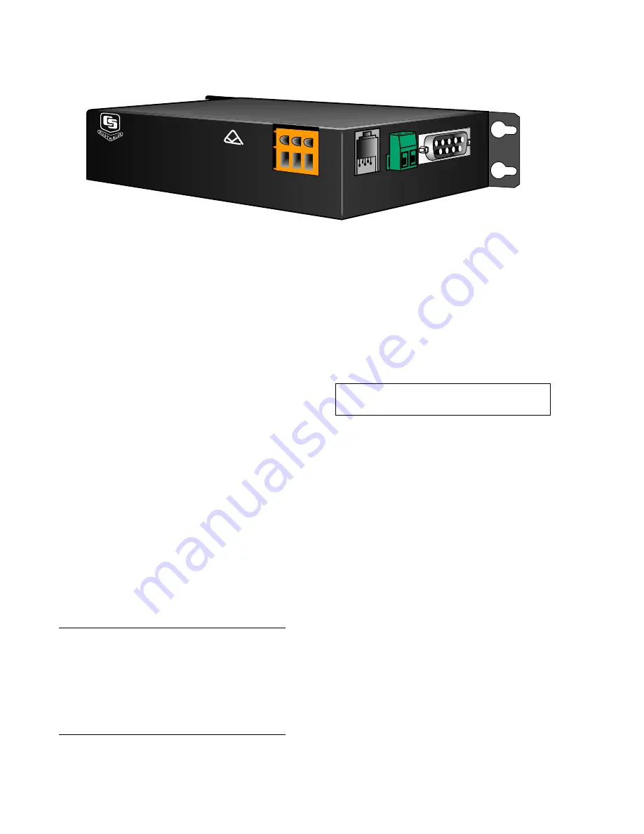
COM200A TELEPHONE MODEM
2
TIP
RING
GND
12V
G
CAMPBELL
SCIENTIFIC
AUSTRALIA
PTY. LTD.
COM200A MODEM
S/N
0002
MADE IN U
SA
REN = 0.5
FIGURE 1. COM200A
3. INSTALLATION
The COM200A is designed to be used with
standard analog telephone lines. It will not work
with a digital telephone line. Connection to
telephone company-provided coin service
(central office implemented systems) is
prohibited. Connection to party line service is
subject to state tariffs.
3.1 CONNECTING TO DATALOGGER
Connect the cable from the telephone RJ11C
jack to the modem as shown in Figure 3. If the
telephone company has not installed surge
protection in the telephone line (no RJ11C jack),
one must install surge protection (Model 6362
or 2372-01) and connect the ring and tip
terminal blocks as shown in Figure 2.
If the Campbell Scientific datalogger
automatically provides 12 VDC, connect the
COM200A to the datalogger with a Campbell
Scientific SC12 cable (Figure 2). When 12 VDC
is not provided on the datalogger's CS I/O 9 pin
connector, 12 VDC and ground need to be
connected via the green power connector on
the side of the COM200A (see Figure 3). Table
1 lists the Campbell Scientific dataloggers that
require direct 12 VDC connection to the
COM200A.
Table 1. Dataloggers that Require Direct
12 VDC Connection to COM200A
CR10(X) w/ silver wiring panel
CR10(X) w/ black CR10 wiring panel (P/N 8032)
21X(L)—serial number 13,442 or lower
CR500
serial number 1764 or lower
CR7—700X serial number 2778 or lower
BDR301 and BDR320
3.2 CONNECTING TO EARTH GROUND
Connect the green 14 awg grounding wire
(provided with the COM200A) to the grounding
terminal (GND) on the COM200A and to the
enclosure’s earth ground connection. If the site
does not have a grounded enclosure, then
connect the ground wire directly to an earth
ground connection. The datalogger ground
should also be tied to the earth ground.
CAUTION:
The modem must be grounded
for its transient protection to work.
3.3 TELEPHONE TO MD9 OR TELEPHONE TO
RF SYSTEMS
Telephone to MD9 or telephone to radio
systems can be utilized for communicating with
multiple dataloggers through one telephone line.
Nothing additional or special is required for the
telephone part of the link. See the MD9 or RF
Manuals for complete information on their
special requirements.
3.4 TELEPHONE SERVICE
The goal of the telephone company is to provide
you with the best service it can. In order to do
this, it may occasionally be necessary for them
to make changes in their equipment, operations,
or procedures. If you have any questions about
your telephone line, such as how many pieces of
equipment you can connect to it, the telephone
company will provide this information upon
request. Additional technical information for
AUSTEL requirements on the COM200A is
available in Appendix D.
Summary of Contents for COM200A
Page 4: ...TABLES 1 Dataloggers that Require Direct 12 VDC Connection to COM200A 2 ...
Page 14: ...This is a blank page ...
Page 16: ...This is a blank page ...
Page 18: ...This is a blank page ...
Page 20: ...This is a blank page ...
Page 21: ...This is a blank page ...