


2-1
Section 2. Station Installation
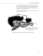
Figure 2-1 shows the typical Bowen ratio installation on the CM10 tripod. The 023A
enclosure, mounting arms, and SP20R solar panel all mount to the tripod mast (1 1/4 in.
pipe, inside diameter) with U-bolts. The size of the tripod allows the heights of the arms to
be adjusted from 0.5 to 3 meters. The mounting arms should be oriented due south to
avoid partial shading of the thermocouples.
The net radiometer is mounted on a separate stake (not provided by Campbell Scientific) so
that the tripod is not a significant portion of its field of view. It should be positioned so
that it is never shaded by the tripod or mounting arms and should be mounted so that it
points south.
2.1 Sensor Height and Separation
There are several factors which must be balanced against each other when
determining the height at which to mount the support arms for the temperature
and air intakes. The differences in temperature and moisture increase with
height, so the resolution on the measurements of the temperature and vapor
gradient will improve the farther apart the arms are.
The upper mounting arm must be low enough that it is not sampling air that is
coming from a different environment upwind. The air that the sensors see
must be representative of the soil/vegetation that is being measured. As a rule
of thumb, the surface being measured should extend a distance upwind that is
at least
100 times the height of the sensors. The following references discuss
fetch requirements in detail: Brutsaert (1982); Dyer and Pruitt (1962); Gash
(1986); Schuepp et al. (1990); and Shuttleworth (1992).
The lower mounting arm needs to be higher than the surrounding vegetation so
that the air it is sampling is representative of the bulk crop surface, and not a
smaller scale effect that might be seen in a row crop if the sensors were down
between rows.
Summary of Contents for Bowen Ratio Instrumentation
Page 10: ...Section 1 System Overview 1 6 This is a blank page ...
Page 20: ...Section 2 Station Installation 2 10 This is a blank page ...
Page 26: ...Section 3 Sample CR23X Program 3 6 This is a blank page ...
Page 30: ...Section 4 Calculating Fluxes Using SPLIT 4 4 This is a blank page ...
Page 34: ...This is a blank page ...
Page 35: ...This is a blank page ...


