background image

 3. 

CAUTION:
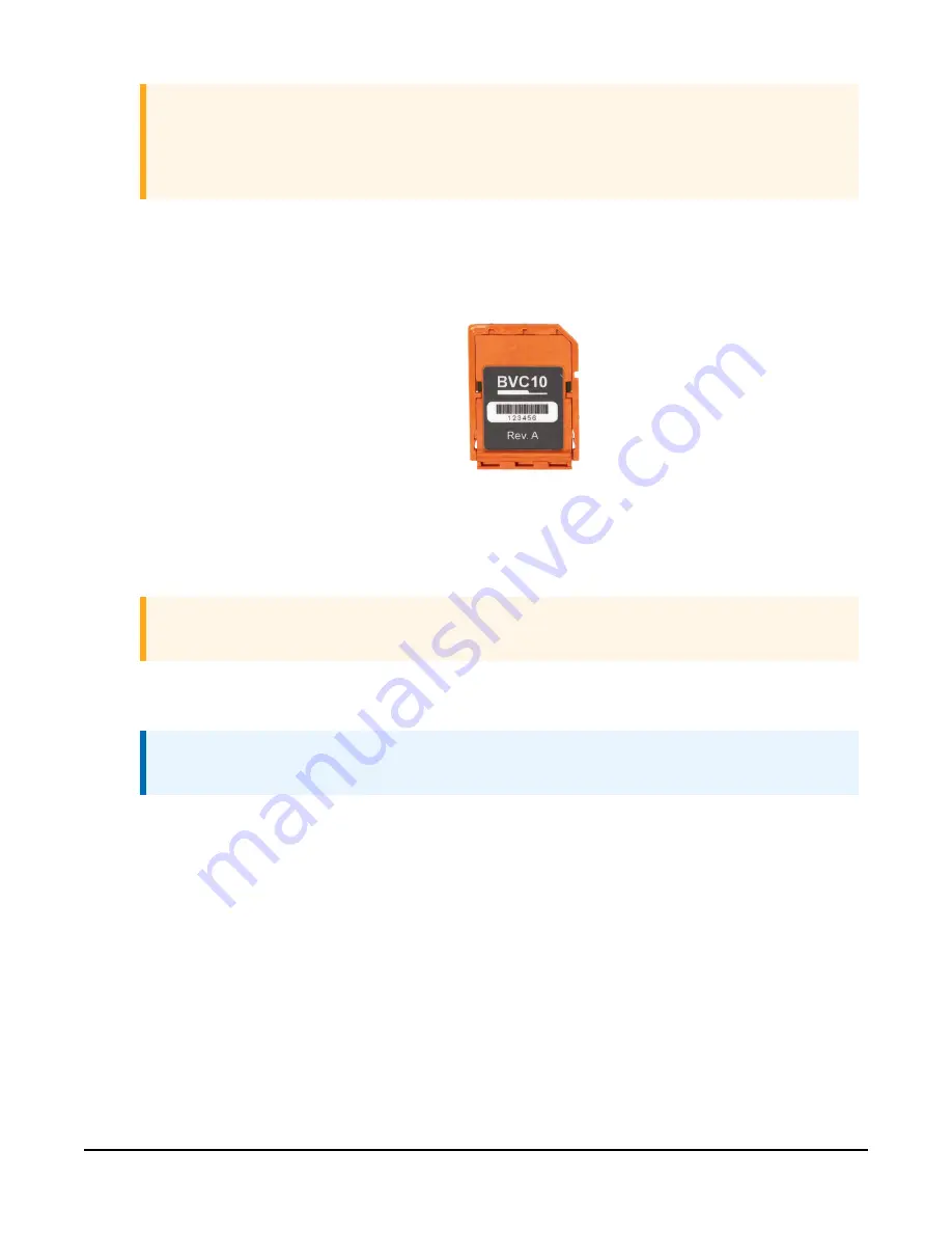
Identify the sensor card installed on the motherboard. 

FIGURE 9-1

 (p. 30) shows  the 

BaroVUE 10 with the installed sensor card. Before removing the sensor card, carefully 
study the device, note its orientation, and read the following description:


l

Sensor card plugs into the silver card socket mounted on the motherboard.


l

Correct sensor-card orientation is with card notch facing down (towards the 
motherboard).

FIGURE 9-2. Card notch in top right corner


l

FIGURE 9-1

 (p. 30) shows the correct orientation of the card. The card revision 

number should be visible.

CAUTION:
If the sensor card is oriented incorrectly, it will not work.

 4.  To remove the sensor card, push the card in towards the socket then release. Spring 

tension pushes the sensor card out of the socket.

NOTE:
The card can be safely removed while the BaroVUE 10 is connected to power.

 5.  Once the sensor card is protruding from the socket, hold the motherboard body with one 

hand and with the other hand, clasp the card body between your fingertips and pull the 
card out of the socket.

 6.  Store the old sensor card in an electrostatic protective package and return it to Campbell 

Scientific for recalibration or general servicing.

 7.  With the old sensor card removed, check the socket and use a damp cloth to clean dirt, 

corrosion, or salt on the socket.

BaroVUE™10 Digital Barometer


31

Summary of Contents for BaroVUE 10

Page 1: ...04 2021 Copyright 2021 Campbell Scientific Inc...

Page 2: ...gramming 10 7 2 2 RS 232 programming 10 7 3 Mounting 11 7 3 1 External air intake 11 7 3 2 Typical mounting 12 7 3 3 ENC100 mounting 13 7 3 4 DIN rail mounting 14 8 Operation 15 8 1 Factory settings 1...

Page 3: ...cknowledge active command a 35 B 1 2 Send identification command al 35 B 1 3 Start verification command aV 36 B 1 4 Address query command 36 B 1 5 Change address command aAb 36 B 1 6 Start measurement...

Page 4: ...and use of this product is in accordance to the manufacturer s instructions recommendations and intended use l Although the BaroVUE 10 is rugged it should be handled as a precision scientific instrum...

Page 5: ...Immediately check package contents against the shipping documentation Contact Campbell Scientific about any discrepancies The following components are included with all BaroVUE 10 assemblies Table 3 1...

Page 6: ...calibration costs The BaroVUE 10 is a fully digital sensor Electronics within the BaroVUE 10 control the measurement made by the sensor element apply the calibration coefficients average the readings...

Page 7: ...5 QuickStart A video that describes data logger programming using Short Cut is available at www campbellsci com videos cr1000x data logger getting started program part 3 Short Cut is an easy way to p...

Page 8: ...asure the sensor every hour or every scan The Barometric pressure and Temperature default to hPa and deg C respectively These can be changed by clicking the Barometric pressure or Temperature box and...

Page 9: ...lick Finish and save the program Send the program to the data logger if the data logger is connected to the computer 9 If the sensor is connected to the data logger check the output of the sensor in t...

Page 10: ...idity 0 to 97 non condensing Supply voltage 9 to 28 VDC Current consumption at 12 VDC Idle 200 A 350 A RS 232 enabled Active 5 mA Housing material Polybutylene terephthalate PBT and polycarbonate PC I...

Page 11: ...rison to international standards NIST 7 Installation If you are programming your data logger with Short Cut skip Wiring p 8 and Programming p 10 Short Cut does this work for you See QuickStart p 4 for...

Page 12: ...me data logger control or U terminal Each must have a unique SDI 12 address Valid addresses are 0 through 9 a through z and A through Z For CR6 and CR1000X data loggers triggering conflicts may occur...

Page 13: ...s are provided in the following sections Downloadable example programs are available at www campbellsci com downloads barovue10 example programs 7 2 1 SDI 12 programming The SDI12Recorder instruction...

Page 14: ...the enclosure must vent to the atmosphere not be hermetically sealed which may require the addition of a vent hole on the outer wall The preferred method is to use a two plate pressure port such as th...

Page 15: ...pical mounting CAUTION To prevent condensation install the sensor in an environmentally protected enclosure complete with desiccant Change desiccant at regular intervals The BaroVUE 10 is typically mo...

Page 16: ...the BaroVUE 10 in its own enclosure see FIGURE 7 4 p 14 The ENC100 is a small enclosure with dimensions of 17 x 14 x 10 cm 6 7 x 5 5 x 3 9 in It includes a compression fitting for cable entry a vent f...

Page 17: ...mounted to a DIN Rail using the DIN Rail mounting kit purchased separately The DIN Rail mounting kit contains the following parts Table 7 4 DIN rail components Quantity Description 1 BaroVUE 10 DIN r...

Page 18: ...n This section discusses the following 8 1 Factory settings 16 8 2 SDI 12 commands 16 8 3 Quality metric 17 8 4 Correcting pressure to sea level 18 8 5 Device Configuration Utility 18 8 6 RS 232 polle...

Page 19: ...command follows the same pattern as an M command with the exception that it does not require the data logger to pause its operation until the values are ready Rather the data logger picks up the data...

Page 20: ...ture 3 Quality Metric 1 mm Hg 2 C 3 N A aM4 aC4 aMC4 or aCC4 1 Pressure 2 Temperature 3 Quality Metric 1 psia 2 F 3 N A Returns the SDI 12 address 8 3 Quality metric For each pressure value the BaroVU...

Page 21: ...level Use the following equation to find the difference dP in pressure between the sea level and the site This equation assumes U S Standard Atmosphere and dry air Wallace J M and P V Hobbes 1977 Atmo...

Page 22: ...1 Open the main case by unclipping the latch and opening the main door FIGURE 8 1 BaroVUE 10 with main door open 2 Open Device Configuration Utility BaroVUE 10 Digital Barometer 19...

Page 23: ...to a computer USB port See FIGURE 8 1 p 19 6 Select the Communication Port in the left panel BaroVUE10 will appear in the selection dialog NOTE It may take a few seconds for the Communication Port to...

Page 24: ...Connect to access the Settings Editor 8 Click the Live Data tab to view real time measurements The Quality Metric Sample value should be greater than 5 see Quality metric p 17 BaroVUE 10 Digital Barom...

Page 25: ...ferent value then click Apply 10 Click the RS 232 tab to change the RS 232 Mode Baud Rate Parity Continuous Mode Sample Period and Continuous Mode Measurement Units After changing settings click Apply...

Page 26: ...y p 18 4 Click the Send OS tab 5 Click Start 6 Select the file It will have an a43 extension 7 Click OK The operating system will start downloading When download is complete the BaroVUE 10 will restar...

Page 27: ...ure 2 Temperature 3 Quality Metric 1 hPa 2 C 3 not applicable N A M1 1 Pressure 2 Temperature 3 Quality Metric 1 kPa 2 C 3 N A M2 1 Pressure 2 Temperature 3 Quality Metric 1 inHg 2 F 3 N A M3 1 Pressu...

Page 28: ...ommunication settings to match the device If the device settings are unknown use the recovery mode to reconfigure the device settings see Recovery mode p 27 5 Press enter several times until BaroVUE10...

Page 29: ...navigate to the main menu type and press enter l To exit without saving changes navigate to the main menu type and press enter CAUTION The menu times out after 30 seconds and unsaved changes are lost...

Page 30: ...A M1 1 Pressure 2 Temperature 3 Quality Metric 1 kPa 2 C 3 N A M2 1 Pressure 2 Temperature 3 Quality Metric 1 inHg 2 F 3 N A M3 1 Pressure 2 Temperature 3 Quality Metric 1 mmHg 2 C 3 N A M4 1 Pressur...

Page 31: ...port 4 Open a terminal program and set the communication settings to the factory defaults Factory settings p 16 5 Continue to press enter until BaroVUE10 appears 6 Type and press enter to view the ma...

Page 32: ...eck the voltage to the sensor If a switched 12V terminal is used temporarily connect the red wire to a 12V terminal non switched for test purposes l Verify the BaroVUE 10 SDI 12 address matches the ad...

Page 33: ...ell Scientific for your replacement sensor card and take this newly calibrated card with you to the site of the BaroVUE 10 installation CAUTION Before handling the BaroVUE 10 wash hands and wear glove...

Page 34: ...If the sensor card is oriented incorrectly it will not work 4 To remove the sensor card push the card in towards the socket then release Spring tension pushes the sensor card out of the socket NOTE T...

Page 35: ...or card into the socket until it will not go any further 12 Before closing the main case double check that the card is inserted in the correct orientation Refer to FIGURE 9 1 p 30 13 Close the main ca...

Page 36: ...for additional refinement NOTE Once the file is edited with CRBasic Editor Short Cut can no longer be used to edit the program it created 2 To add the Short Cut wiring information into the new CRBasi...

Page 37: ...ffer Mode videos B 1 SDI 12 command basics SDI 12 commands have three components l Sensor address a a single character and the first character of the command Use the default address of zero 0 unless m...

Page 38: ...CR LF Extended Commands aXNNN a values CR LF 1 Information on each of these commands is given in the following sections B 1 1 Acknowledge active command a The Acknowledge Active command a is used to t...

Page 39: ...til verification information is available n the number of values to be returned when one or more subsequent D commands are issued B 1 4 Address query command Command requests the address of the connec...

Page 40: ...o values within the next 35 seconds 0 CR LF Within 35 seconds sensor 0 indicates that it has completed the measurement by sending a service request to the data logger 0D0 The data logger immediately i...

Page 41: ...e of data returned and the number of values a sensor returns the data logger may need to issue aD0 up to aD9 to retrieve all data A sensor may return up to 35 characters of data in response to a D com...

Page 42: ...ransparent mode and change the SDI 12 address of an SDI 12 sensor The steps shown in Changing an SDI 12 address p 39 are used with most Campbell Scientific data loggers B 2 1 Changing an SDI 12 addres...

Page 43: ...press Enter In this example the sensor is connected to C3 The response Entering SDI12 Terminal indicates that the sensor is ready to accept SDI 12 commands 10 To query the sensor for its current SDI...

Page 44: ...changed from 0 to B 12 To exit SDI 12 transparent mode click Close Terminal NOTE The transparent mode for the CR6 CR3000 CR800 series CR300 series and CR1000 data loggers is similar to that shown for...

Page 45: ...ther manufacturer s products that are resold by Campbell Scientific are warranted only to the limits extended by the original manufacturer Refer to www campbellsci com terms warranty for more informat...

Page 46: ...ion or Repair Reference number contact your CAMPBELL SCIENTIFIC regional office Please write the issued number clearly on the outside of the shipping container and ship as directed For all returns the...

Page 47: ...rohibit climbing by other persons Take reasonable precautions to secure tripod and tower sites from trespassers l Use only manufacturer recommended parts materials and tools Utility and Electrical l Y...

Page 48: ...nfo campbellsci fr www campbellsci fr Germany Location Phone Email Website Bremen Germany 49 0 421 460974 0 info campbellsci de www campbellsci de India Location Phone Email Website New Delhi DL India...

Reviews: