

A
A
A
A
A
2
1
A
2
3
A
B
2
3
1
A
2
3
1
A
A
A
A
A
B
NO
NO
YES
A
B
A
A
Series MD
Air Treatment
Use and maintenance instructions
Made in Italy
93-7537-
5103
rev.A
This product is in compliance with the requirements stated in the following standards
and/or technical specifications:
- EN ISO 4414:2010 Pneumatic fluid power - General rules and safety requirements
for systems and their components
• Use the product complying the technical specification contained in the section “General
characteristics” and in Camozzi product catalogue.
• Unless special applications are allowed, do not use the product in environment where the
product might be in direct contact with corrosive gases, chemicals, salted water, steam or water.
• Avoid, where possible, the installation devices:
- in closed and narrow spaces;
- where there is direct exposure to sunlight (provide shielding where necessary);
- in proximity of any heat sources or in areas subject to sudden change in temperature.
6 Use limitation
• Before performing any maintenance on module/modules is to disconnect the compressed air
source allow the release of any residual pressure inside them.
• For some type of modules, where is not described “using instruction” in this document (Cap. 4),
revisions or maintenance are possible only at a service center Camozzi spa.
7 Maintenance
At the end of the cycle of the product, it is recommended to separate the materials in order to
recycle them. Dispose of the product and the packaging material according to current environmental
standards of your country.
8 Ecologic information
The EC Compliance Declarations can be downloaded from
www.camozzi.it
1 General safety instructions
The correct assembly and start-up of any pneumatic appliances within a system is the responsibility
of the system designer or the person whom establishes the technical specifications.
As the products, described in this manual, can be used in different operating conditions, their
correct use inside a specific pneumatic system has to be based on their technical characteristics to
meet your specific requirements, after having been submitted for analysis and/or tests.
The performance and safety of the system is the responsibility of the designer who establishes the
function of the components within the system.
The air treatment unit (or single module) must only be used for servicing compressed air systems
in the industrial sector. The product is intended to be used to a standard and you must comply
with these instructions, all accompanying documents and with the relevant national accident
prevention regulations of the site.
The assembly, use and maintenance of pneumatic systems must only be carried out by qualified
personnel or by an instructed person under the direction and supervision of qualified personnel.
Do not interfere with the machine or appliance without having checked whether the working
conditions are safe.
Before the installation, maintenance or modification, make sure that any safety features are activated,
then interrupt the power supply (if necessary) and the system pressure supply.
Make sure all of the residual compressed air in the system and any stored energy (liquid pressure,
spring, condenser, gravity) is removed.
After installation, maintenance or conversion, the pressure and power supplies (if required) must
be reconnected to the product.
The product should then be tested for leaks and correct functionality. If the product leaks or
malfunctions, do not operate the product. This air treatment unit (or single module) has been developed
and tested exclusively to be used with clean and dry compressed air, free of chemical additives.
Operation with other substances or additives besides the specified ones is not recommended and
needs to be authorized by Camozzi.
The air treatment unit (or single module) must not be operated in aggressive ambient air (presence
of solvent vapors, etc.). Furthermore it must be checked daily for tears, cracks, deformations, or
other damage. If the unit shows any of the faults described, do not operate the system or if it is
in use, immediately interrupt its operation and exchange the damaged component. Remove any
accumulation of dirt close to the observation windows of the reservoirs where necessary to enable
a visual control of the correct function of the product. If it proves difficult to remove the dirt, replace
the part. When interrupting the supply, a residual pressure may remain on the secondary side of
the regulators (or filter-regulators) that may allow the appliance to continue to operate.
The designer therefore has to add an exhaust component to remove this pressure.
The product can only be put back into operation if it complies with the indicated specifications.
If for any reason these specifications are not respected, the product can only operate after authorization
has been given by Camozzi.
The instructions contained in this manual must be followed together with the instructions and
other information, related to the here described product, available in:
- Website http://www.camozzi.com - Camozzi general catalogue - Camozzi technical support.
3.6
Panel mounting with nut (FR, R, M)
- Place the nut (
A
) on the thread below the setting
knob of module (FR, R, M) and tighten.
3.10
Assembly pressure gauge
- Insert and screw pressure gauge in the threads
holes G1/8 present on front/back side of modules
(secondary outputs).
Tightening torque (
B
): 2,5 Nm Max
3.11
Assembly fittings on secondary outputs (front/back side)
- Insert and screw fittings in the threads holes G1/8
present on front/back side of modules (secondary outputs).
Note
: from secondary output sit is possible carry
out air with function of the module applied
(except for filters FC e FCA in which the air
from secondary outputs is not filtrated).
Tightening torque (
B
): 2,5 Nm Max
3.12
Assembly pressure switch / fittings on secondary outputs (up side)
- Insert and screw pressure switch / fittings
in the threads holes G1/8 present on up side
of modules (secondary outputs).
Tightening torque (
B
): 2,5 Nm Max
3.13
Assembly silencers / fittings on secondary outputs (down side)
- Insert and screw pressure switch / fittings
in the threads holes G1/8 present on down side
of modules (V01, V16, V36, B) (secondary outputs).
Tightening torque (
B
): 10 Nm Max
3.14
Assembly fitting on threads connections IN / OUT
We suggest to assembly fittings on the thread
connections IN / OUT before fixing module
or assembled modules on the panel or wall.
Tightening torque: 20 Nm Max
3.15
Turn 180° the bowl
- Push to open and hold in the unlocking clip (
A
),
rotate the bowl clockwise until it stops and move
it down from the body of module.
- Rotate the bowl 180°.
- Insert the bowl again in the body and rotate
it anti-clockwise until it stops; it is not necessary
push the clip to close.
Note
: this instruction can do for all modules with bowl,
so filters (F, FC, FCA), filter-regulator (FR) e lubricator (L).
> ATTENTION! In the filter-regulator (FR),
we recommend always to reset to zero the pressure setting
(anti-clockwise of knob to zero) before remove the bowl.
• During the product’s unpacking be careful not to damage it.
• Check that no damages, due to transportation or storage, are present.
• Before start-up, check the correct installation of all components. A non correct installation can
damage the air treatment unit and be the cause of serious injury.
• The components must be fixed properly, using, where available, the applicable Camozzi brackets
so that the device remains fixed even when the regulator operates at high frequency or in the
presence of strong vibrations.
• If the system is not equipped with soft start valves, sudden pressures could exist at the moment
of start-up, that could be the cause of cylinder movements. Make sure that these cylinders
are in their end position or that they do not cause any danger.
• In the presence of strong vibrations provide special devices / systems that can reduce the effect
on the component.
• When the component has been installed ensure that all pipes are properly connected.
5 Start - up
2 General characteristics and use conditions
Construction
modular, compact
Max inlet pressure
16 bar (V16: 10bar)
Fluid
air, inert gas
Ambient temperature
0 ÷ 50 °C
Mounting
in line, panel mounting
Port size IN (1) /OUT (2)
G1/8, G1/4, G3/8, Ø6, Ø8, Ø10
Lateral port
G 1/8
Range of regulated pressure (R, M and FR)
0÷2, 0÷4, 0,5÷7, 0,5÷10 bar
Range of filtration (F, FC, FCA)
25µm, 5µm, 1µm, 0,01µm, CA
3 Assembly instructions
3.1
Assembly of external connections
(G1/8, G1/4, G3/8, Ø6, Ø8, Ø10 etc.)
- Insert the connection (
A
) in the seat
of the module (side with O-ring).
- Insert and tighten the two screws (
B
)
Repeat on the opposite side of the module
or the terminal module assembly.
Tightening torque (
B
): 1 Nm Max
A
B
B
YES
YES
NO
3.2
Assembly of connection nipple between modules
- Insert the connection nipple (
A
)
in the seats of the module to assembly.
- Insert and tighten the two screws (
B
)
in the first module the two screws (
B
)
in the next module.
Repeat the operation to assembly more modules.
Tightening torque (
B
): 1 Nm Max
B
B
A
3.9
Mounting module to wall with bracket
- Fix the bracket (
B
) to the wall.
- Insert the screws M4x50 (
A
) of the kit (MD1-P)
in the seats present in the module and tighten
into holes M4 of the bracket.
We suggest use of brackets In the wall mounting
of modules as filters, filter-regulator, lubricator
(F, FC, FCA, FR, L), to facilitate the operations
of assembly and disassembly of the bowl.
Tightening torque (
B
): 2 Nm Max
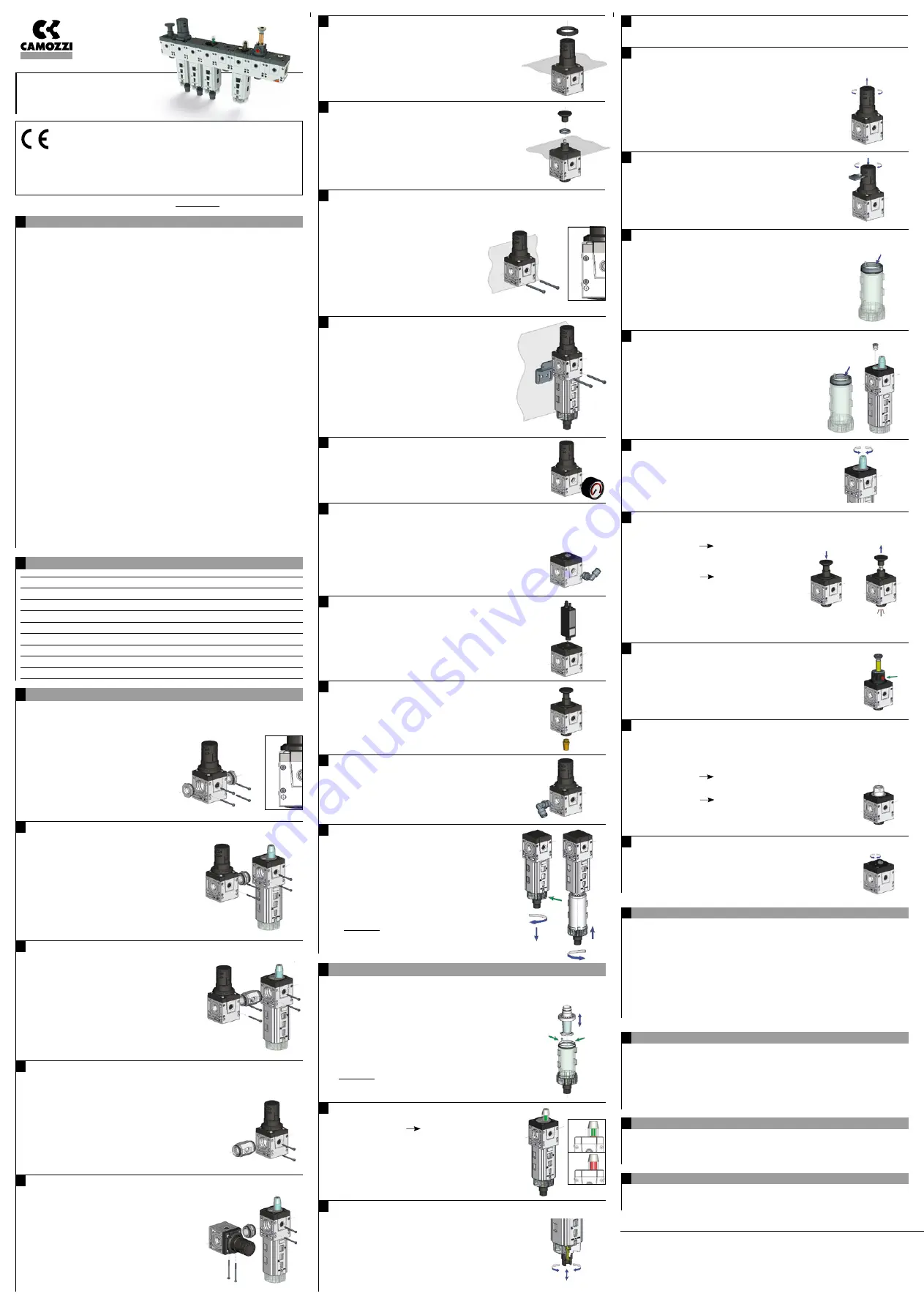
4.6
Locking the pressure regulator valve (FR, R, M)
To prevent unauthorized changes in pressure setting
(see cap. 4.5), the knob of the pressure regulator valve
can be secured with one or more locks:
- Lift and rotate the knob clockwise or anti-clockwise
and set the pressure.
- Press the knob downwards.
- Hook the lock in one or more of the seat present on the knob.
4.7
Filling the oil reservoir of the lubricator with interruption of the air in line
- Interrupt the air in the line.
- Push to open and hold in the unlocking clip
(see cap. 3.15
Turn 180° the bowl
),
rotate the bowl clockwise until it stops
and move it down from the body of module.
- Fill with oil the bowl until “MAX OIL” sign.
- Insert the bowl again in the body and rotate
it anti-clockwise until it stops;
it is not necessary push the clip to close.
- Let air flow into the line.
4.8
Filling the oil reservoir of the lubricator without interruption of the air in line
- Depressurize the bowl by unscrewing the plug (
A
).
- Push to open and hold in the unlocking clip
(see cap. 3.15
Turn 180° the bowl
),
rotate the bowl clockwise until it stops
and move it down from the body of module.
- Fill with oil the bowl until “MAX OIL” sign.
- Insert the bowl again in the body and rotate
it anti-clockwise until it stops; it is not necessary
push the clip to close.
- Pressurize the bowl by screwing the plug (
A
).
4.9
Setting the oil amount
- The percentage of oil can be varied by using
the adjustment screw (
A
).
4.10
Manual isolation 3/2 way valve
- The manual isolation valve, Series MD,
are used to pressurize or depressurize a system line.
To open the valve 1
2:
- Press down the active element (
A
);
with the opening of the air connects the IN (
1
)
with the OUT (
2
).
To close the valve 2
3:
- Pull up the active element (
A
);
with the closing of the air in IN,
there is the simultaneous output
of the air from OUT (
2
) to exhaust (
3
).
When the valve is in a closed position, it is possible
to insert a lock in a seat to prevent it being accidentally opened.
3.8
Mounting module to wall with screws
- Insert screws M4 (
A
) in the seats present
in the module and tighten into holes M4 previously
made in the wall.
As screws M4 use kit MD1-D, screws M4x50
o longer. In the wall mounting of modules
as filters, filter-regulator, lubricator
(F, FC, FCA, FR, L), to facilitate the operations
of assembly and disassembly of the bowl,
we recommend the use of bracket (MD1-P)
which space the module, and so bowl,
from the wall itsel.
Tightening torque (
B
): 2 Nm Max
4.5
Pressure setting (FR, R, M)
The pressure regulator valve of the Series MD
are used to regulate the air pressure to the desired value,
but obviously not higher than network pressure.
- Lift and rotate the knob (
A
) clockwise
or anti-clockwise and set the pressure.
In any case the right calibration of the pressure
must be set upwards and then lock the rotation.
The air flow is from IN (
1
) to OUT (
2
) as indicated
on the modules (FR, R); in manifold regulator (M)
the OUT are in front/back side.
3.7
Panel mounting with nut (V01)
- Unscrew and remove the active element (
A
).
- Place the nut (
B
) on the thread of the cup
of module V01 and tighten.
- Replace, screwing, the active element (
A
)
previously removed.
Note
: use nut M16x1
4.4
Semi-automatic depressure condensate drain SMD (F, FC, FR)
- To drain the condensate automatically when needed, with or without pressure.
3.3
Assembly of connection nipple with thread derivations between modules
- Insert the connection nipple with thread derivations (
A
)
in the seats of the module to assembly.
- Insert and tighten the two screws (
B
) in the first
module the two screws (
B
) in the next module.
Note
: during the assembling, it is possible
to orient the connection nipple with thread
derivations with steps of 45° rotation.
Tightening torque (
B
): 1 Nm Max
3.4
Assembly of connection nipple with thread derivations as external position
- Insert the connection nipple with thread derivations (
A
)
in the seat of the, maintaining the female thread
present in the nipple external to the module.
- Insert and tighten the two screws (
B
).
Note
: during the assembling, it is possible to orient
the connection nipple with thread derivations with steps
of 45° rotation. The connection nipple with thread
derivations can assembly as first element but also
as last element.
Tightening torque (
B
): 1 Nm Max
B
B
B
B
A
B
B
A
Camozzi spa
Società Unipersonale
Via Eritrea, 20/I
25126 Brescia - Italy
Tel. +39 030 37921
Fax +39 030 2400430
www.camozzi.com
Technical assistance
Products inquiries and
requests for support
Tel. +39 030 3792790
Product Certification
Information concerning
product certifications, EC standards,
conformity declarations and instruction
4 Using instructions
4.1
Inserting / changing the filter element (F, FC, FCA)
- Push to open and hold in the unlocking clip
(see cap. 3.15
Turn 180° the bowl
),
rotate the bowl clockwise until it stops and move
it down from the body of module.
- Remove the filter element working on the teeth of the bowl (
A
).
- Insert again new filter element in the bowl until the teeth (
A
)
fix the element.
- Insert the bowl again in the body and rotate it anti-clockwise
until it stops; it is not necessary push the clip to close.
> ATTENTION! In the filter-regulator (FR), we recommend
always to reset to zero the pressure setting
(anti-clockwise of knob to zero) before remove the bowl.
4.2
Visual check of the life of filter element (F, FC, FCA)
- Visual check is GREEN = filter element work correctly.
- Visual check is GREEN
RED = filter element
begins to get clogged, it should replace it.
- Visual check is RED = filter element is completely
clogged, it necessary replace it.
4.11
Electro-pneumatic isolation 3/2 way valve
The electro-pneumatic isolation valve, Series MD,
are used to pressurize or depressurize a system line.
The electro-pneumatic isolation valve is activated
by using a solenoid valve (
A
) that works only
when the electric solenoid coil is operated.
This type of isolation valve is, also, equipped
with a manual override (
B
).
4.12
Pneumatic isolation 3/2 way valve
The pneumatic isolation valve, Series MD,
are used to pressurize or depressurize a system line.
The pneumatic isolation valve is activated using
the upper base (
A
) on which must be connected, via thread,
another external valve that provides the control signal.
To open the valve 1
2:
- Provide pneumatic signal from an external valve; with the opening
of the air connects the IN (
1
) with the OUT (
2
).
To close the valve 2
3:
- Remove pneumatic signal from an external valve;
with the closing of the air in IN, there is the simultaneous
output of the air from OUT (
2
) to exhaust (
3
).
4.13
Setting the fill time of the soft start valve
The soft start valve regulates the gradual inlet
of the air in the line of pneumatic system during
its start phase.The pressurization time is regulated
by using the adjustment screw (
A
).
4.3
Semi-automatic / manual condensate drain (F, FC, FR)
- In the manual position, to drain the condensate, you have
to rotate the nose nut (
A
) clockwise and pus hit upwards.
- Once the liquid has been ejected, release the nose nut (
A
)
and rotate it anti-clockwise.
- In semi-automatic position, to drain the condensate each time
there is no pressure; it is also possible to drain the condensate
when pressure is on the unit by pushing the nose nut (
A
) upwards.
- To change from the semi-automatic to manual position,
rotate the nose nut (
A
) clockwise, vice versa rotate the nose
nut (
A
) anti-clockwise.
3.5
Module orientation respect to the direction of the air line
During the assembling of the connection nipple
between modules, it is possible to orient the module
with steps of 90° rotation.
Module orientations are permitted for all modules
except filters (F, FC, FCA) and lubricator (L) that
have to maintain vertical orientation of the bowl (down).
A
A
B
OK
NO
A


