background image

10

• DISPLAY

• MARKER

WIDE

NORMAL

CINEMA

FULL

DIMMER
LANGUAGE
DIRECTION
DISPLAY

MARKER

RESET

ENGLISH

0

˚

FULL

OFF

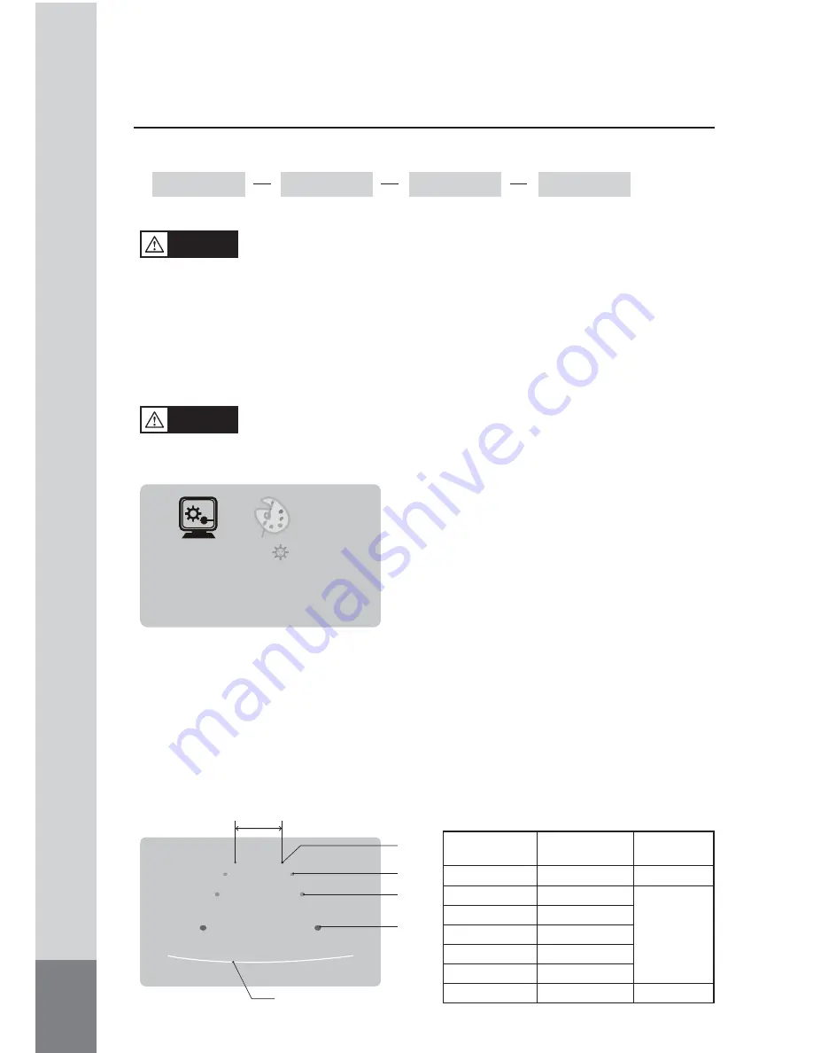
-  The onscreen distance markers should be considered as a general reference to assist 

the  driver  in  assessing  the  distances  depicted  on  the  screen.  The  distance  markers 
have been designed based on the “CCD camera installation conditions” listed in the 
next  section,  but  differences  in  vehicle  design  and  construction  may  result  in  the 
actual installation condition or location being different from the conditions listed. In 
such cases, the display location should be set at the closest marker No. 

- Distance markers cannot be set if non CAMOS cameras are used.

Warning

-  The markers may not indicate the exact position of the bumper, the vehicleʼs width or 

the distance to the rear. Use as a reference only.

Caution

(1)   Press MENU button on CAM1, full screen mode.

(2)  Press MODE button and select MARKER. 

(3)  Then, press [DOWN/UP] button on the monitor 

or [

◀▶

] button on the remote control, select 

ON. 

*  It is set OFF from the factory.

MARKER
SELECT

P1

7m

5m

3m

1m

Bumper position

(From bumper

toward rear)

Vehicle width

■  CCD camera installation conditions 

(distance marker input conditions)

(Unit:mm)

Marker No.

(Pattern)

Camera Install

Height

Vehicle

Width

P1

P2

P3

P4

P5

P6

P7

2,000

2,250

2,500

2,750

3,000

3,250

3,500

2,500

2,300

2,500

<MARKER SELECT>

(1)  Press MENU button and select MARKER SELECT menu. 

(2)  P

ress [DOWN/UP] button on the monitor or [

◀▶

] button on the remote control,

  and 

switch marker pattern.

*  Distance marker function setting is only possible when MARKER is selected on CAM1, 

full screen mode. 

Summary of Contents for CM-708R

Page 1: ...LANGUAGE VEHICLE INSTRUCTION MANUAL CM 708R 7 TFT LCD COLOR MONITOR Thank you for purchasing this product For proper usages and application please read this instruction manual thoroughly PRINTED IN KO...

Page 2: ...2 CONTENTS SAFEGUARD INSTRUCTIONS 3 FEATURE 5 BOX CONTENTS 5 FUNCTION OF EACH PART 6 FUNCTIONS 8 CHANGING REMOTE CONTROL BATTERY 12 CONNECTIONS 13 INSTALLATION 14 SPECIFICATION 15...

Page 3: ...r a long time It may case fire by short circuit due to heating Do not place near magnet It may cause malfunction and trouble Should install while power off After install products connect DC jack It ma...

Page 4: ...lfunction and injury can not get warranty Make inquiries to agent for repair and checkup WARNING Do not put the product in place where sudden temperature increasing and should use on optimum voltage t...

Page 5: ...d on screen OSD function PWM volume control Mode selection function Low energy consuming rate Language Display Selection KOR JPN GER ENG SPA FRE ITA 4 Screen Mode FULL WIDE NORMAL CINEMA Free voltage...

Page 6: ...OR MONITOR Power or Stand by status display Power ON OFF button CAM1 CAM2 AV selection function SETUP PICTURE selection function SOUND MENU level control FUNCTION OF EACH PART S BY LED POWER MODE MENU...

Page 7: ...ecting MENU and changing functions Changing volume or MENU level Moving Up Down on MENU Mute mode On Off Displaying the current channel and volume level Adjusting the screen setting POWER MODE MENU VO...

Page 8: ...and it is disappearing 5 seconds after setting FUNCTIONS POWER 1 ON OFF 1 Press POWER button to the power STAND BY state is OFF 2 Press POWER button again to off the power STAND BY state is ON It is...

Page 9: ...R LANGUAGE DIRECTION DISPLAY MARKER RESET ENGLISH 180 FULL OFF 9 MENU 4 SETUP PICTURE CAMERA 2 Press MODE button to select SUB MENU UP DOWN button to change SUB MENU DIMMER 1 SETUP LANGUAGE ENGLISH DE...

Page 10: ...non CAMOS cameras are used Warning The markers may not indicate the exact position of the bumper the vehicle s width or the distance to the rear Use as a reference only Caution 1 Press MENU button on...

Page 11: ...N UP button on the monitor or button on the remote control and switch marker pattern H 10 10 V 12 12 Default setting H 0 V 0 4 After 10 seconds set up screen disappears and set up finishes If there is...

Page 12: ...cted menu in red 2 Push UP DOWN button to change the settings of the diferent menu points 3 CAMERA 1 Press the mode button to choose CAM1 CAM2 will turn red 2 Press the VOLUME UP DOWN button NORMAL MI...

Page 13: ...3 This function can be operated by the remote control MUTE 6 When press the AUTO PIC button PICTURE SETUP menu is displayed on screen AUTOPIC 5 RECALL 7 1 Press MUTE button to mute sound and display m...

Page 14: ...NITOR CHANGING REMOTE CONTROL BATTERY 1 Pull the battery cover to the direction of the arrow 2 Place a battery with the sign upward No CR2025 3 Put the battery case back into the remote control in the...

Page 15: ...A 1 CAMERA 2 BLACK CAMERA1 GREEN CAMERA2 VIDEO AUDIO DC INPUT CAMERA OPTION CIGAR CABLE MDM 105A BLACK CAMERA 1 Priority FOR REAR VIEW Connect this line to of reverse light lamp GREEN CAMERA 2 FOR SID...

Page 16: ...R INSTALLATION 1 Please set the place for Monitor installation Clean the place where to install stand and install stand firmly after removing protect tape of stand bottom 2 Fix the stand with enclosed...

Page 17: ...PERATURE DIMENSION WEIGHT SCREEN SIZE DISPLAY FOMAT BRIGHTNESS Contrast ratio ACTIVE AREA VIEW ANGLE VOLTAGE CONSUMPTION HORIZONTAL VERTICAL 17 78 cm 7 0 inch 800 H x 3 RGB x 480 V 400 cd m2 500 1 154...

Page 18: ...MEMO...

Page 19: ...MEMO...

Page 20: ...INSTRUCTION MANUAL...

Reviews: