background image

7

Installation,  Operation  and  Maintenance  Manual

D I S T R I B U T E D   V A L V E S

Procedure

Raised Face

Area

Wafer Body

Lug Body

The following procedure applies to new 
installation between standard ASME B16.5             
pipe flanges.

When replacing a valve from an existing 
installation, clean the flange faces of any           
residual gasket material before starting.

Actuation should not be removed from the            
valve for installations unless the actuator          
must be transferred during replacement.

1.

Remove protective covers from valve.                     
Be sure valve is completely closed.

2.

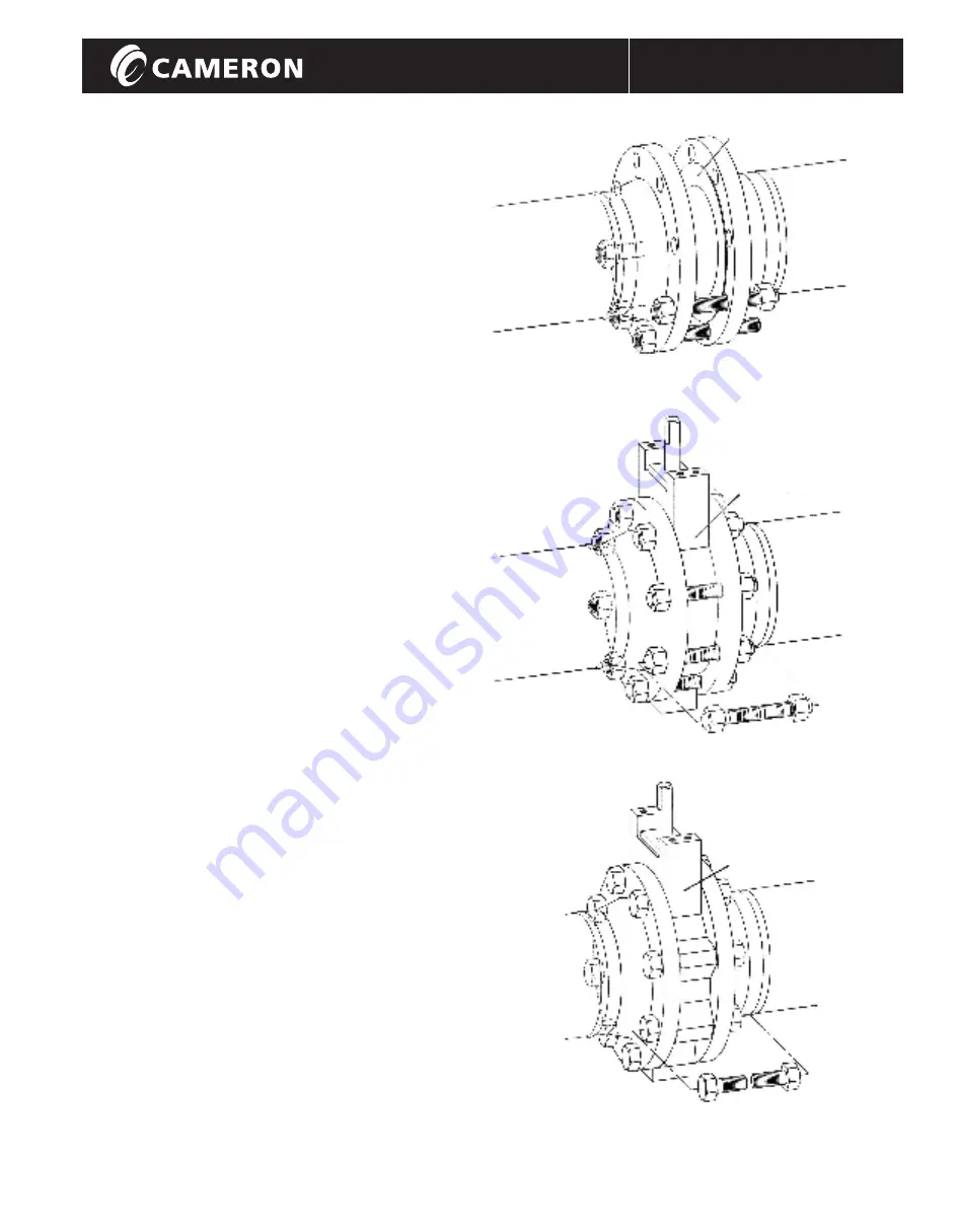
When installing wafer body valves,                 
install lower flange bolts without                
tightening (Figure 10). Position valve               
and flange gaskets between flanges,             
within the pocket formed by the flange 
bolts. Install the remaining flange                     
bolts, taking care that the gaskets are                  
centered on the flange faces (Figure 11).

Note: While the WKM 


MA High Performance Butterfly                      
Valve has bi-directional sealing               
capabilities, the preferred position                  
is seat upstream (Figure 4).                        
Handle operated valves or fail close   
valves should be installed seat 
downstream (stem side facing flow).

3.

Lug body valves should be positioned 
between the flanges with gaskets                  
properly centered and then the                 
capscrews inserted (Figure 12).

4.

Carefully check disc clearance by                 
placing the valve in the full open                  
position. Should automated valves be           
difficult or impossible to cycle, check                  
that the raised face of the flange                 
matches the raised area on the valve               
face.

5.

Tighten all bolts or capscrews in a            
crossover or star pattern to insure                      
even sealing (Figures 11 and 12).

6.

Packing gland tightness is pre-tested                  
at the factory. Should stem leakage                 
occur at start-up, the gland can be               
adjusted to stop the leak.                                  
Avoid over tightening which may                         
result in excessive operating torque                         
or premature packing wear.

DynaCentric

Figure 10

Figure 11

Figure 12

WKM-MA-HPBV-IOM

Summary of Contents for WKM MA

Page 1: ...WKM MODEL MA DYNACENTRIC HIGH PERFORMANCE BUTTERFLY VALVE D I S T R I B U T E D V A L V E S Installation Operation and Maintenance Manual WKM Installation Operation and Maintenance Manual WKM MA HPBV IOM ...

Page 2: ...formation 3 Nameplate Information 3 Scope 4 Storage 4 Installation 4 End of Line Service 5 Disc Pipe Clearance 5 Gaskets 6 Flange Bolt and Stud Size 6 Procedure 7 Operation 8 Routine Maintenance 9 Trouble Shooting 9 Cameron s Valves Measurement Group Revised 11 07 WKM MA HPBV IOM Installation Operation and Maintenance Manual WKM MA HPBV IOM ...

Page 3: ...ass 300 Bill of Materials WKM MA HPBV IOM ITEM DESCRIPTION 1 Body 2 Seat Retainer 3 Seat Retainer Screw 4 Stem Disc Spring 5 Stop Pin 6 Stop Pin Plug 7 Stem Bearing 8 Nameplate 9 Gland Retainer 10 Gland Retainer Stud 11 Gland Retainer Nut 12 Body Gasket 13 Upper Stem ITEM DESCRIPTION 14 Disc 15 Lower Stem 16 Stem Pins 17 Disc Spacer 18 Key 19 Stem Retainer Pins 20 Packing Spacer 21 Gland Ring 22 S...

Page 4: ... D V A L V E S Figure 2 Cameron Valves WKM 14 30 Class 150 12 24 Class 300 10 12 Class 600 DynaCentric Butterfly Valve Components Lug body shown wafer body available 4 7 8 7 20 23 10 21 11 9 1 26 25 27 18 13 19 16 17 16 15 14 22 12 2 3 Bill of Materials WKM MA HPBV IOM ...

Page 5: ...al Number 5 Manufacture Date 6 Stem Material 7 Disc Material 8 Seat Material 9 Packing Material 10 Maximum CWP 11 Min Operating Temperature 12 Seat Ratings Class Material Style XX A5XXX XX XXX XX XX 6 600 4 CS ENC 5 LCC 17 4 Stem 6 Ni Cu Stem 04 SS Disc 7 HF 6 O L 07 5 Ni Cr Stem 1 2 4 5 7 6 8 9 10 10 1 2 3 4 6 5 7 10 11 8 9 12 12 Nameplate Information Note Valves with optional materials of constr...

Page 6: ...ttom of the line by a jetting action When such action is desired the valve should be installed seat upstream flow from the seat side of the valve with the integral stop pin in the vertical up position Figure 6 DynaCentric DynaCentric The WKM DynaCentric MA High Performance Butterfly Valve offers all the benefits of a wafer valve smaller size lower price lighter weight and throttling capabilities a...

Page 7: ... 8 150 X 7 90 8 300 X X 7 90 8 600 X X X 7 40 10 150 X 10 00 10 300 X X 9 80 10 600 X X X 9 06 12 150 X 11 90 12 300 X X 11 75 12 600 X X X 11 75 14 150 X 13 06 14 300 X X 13 00 16 150 X 15 00 16 300 X X 14 68 18 150 X 16 87 18 300 X X 16 50 20 150 X 18 81 24 150 X 22 62 24 300 X X 22 06 30 150 X X X 28 02 Table 1 Disc Clearance Before beginning installation note the following Disc pipe clearance ...

Page 8: ... 10 5 8 3 4 10 UNC 12 7 25 24 2 50 6 600 11 1 2 1 8 UNC 12 9 50 24 3 25 8 150 11 3 4 3 4 10 UNC 8 6 75 16 2 25 8 300 13 7 8 9 UNC 12 8 25 24 3 00 8 600 13 3 4 1 1 8 8 UN 12 11 00 24 4 00 10 150 14 1 4 7 8 9 UNC 12 7 25 24 2 50 10 300 15 1 4 1 8 UNC 16 9 50 32 3 25 10 600 17 1 1 4 8 UN 12 8 13 00 4 00 32 4 00 12 150 17 7 8 9 UNC 12 7 75 24 2 50 12 300 17 3 4 1 1 8 8 UN 16 10 50 32 3 75 12 600 19 1 ...

Page 9: ...lange faces Figure 11 Note While the WKM MA High Performance Butterfly Valve has bi directional sealing capabilities the preferred position is seat upstream Figure 4 Handle operated valves or fail close valves should be installed seat downstream stem side facing flow 3 Lug body valves should be positioned between the flanges with gaskets properly centered and then the capscrews inserted Figure 12 ...

Page 10: ...they are in line with the flow stream the valve is open When perpendicular the valve is closed In all cases when the valve is closed the handle is perpendicular to the run of the pipe Figure 13 and when the valve is open the handle is parallel to the pipe Figure 14 Maximum recommended pressure differential for handle operated valves 3 400 psi 4 300 psi 6 150 psi 8 50 psi Worm Gear Operated Worm ge...

Page 11: ...rly Adjust stops to proper setting Build up of solids or roughness on Operate several times to wipe clean or edge of disc disassemble valve and clean disc edge Stem packing is too tight Tighten packing only sufficiently to stop leaks Operator is not installed properly Reinstall operator in proper alignment with valve stem Disc hits on side of pipe Check for proper pipe clearance Seat retainer scre...

Page 12: ...WKM MA HPBV IOM 3250 Briarpark Drive Suite 300 Houston Texas 77042 USA Toll Free 800 323 9160 For the most current contact and location information go to www c a m com Contact your Cameron s Valves Measurement group representative for a Repair Manual D I S T R I B U T E D V A L V E S WKM MA HPBV IOM ...

Reviews: