Appendix E: Flashing the Scanner
113
Appendix
E
: Flashing the Scanner
“
Flashing
” is the term used to describe the procedure that installs a different version of firmware other
than the one with which the Scanner was shipped
.
If changing the firmware is NOT necessary
, the
startup procedure may be initiated. See
, page
Reprogramming the flash memory of the Scanner 1141 with a new version of firmware requires the use
of a loading program. The
WinsLoad or ScanFLASH
program is utilized in a Windows 3.1, 95, 98, NT,
2000 or XP environment.
Preparing to Flash
To change the firmware installed in the Scanner’s Flash memory, a PC with the WinsLoad or
ScanFLASH program is required.
1.
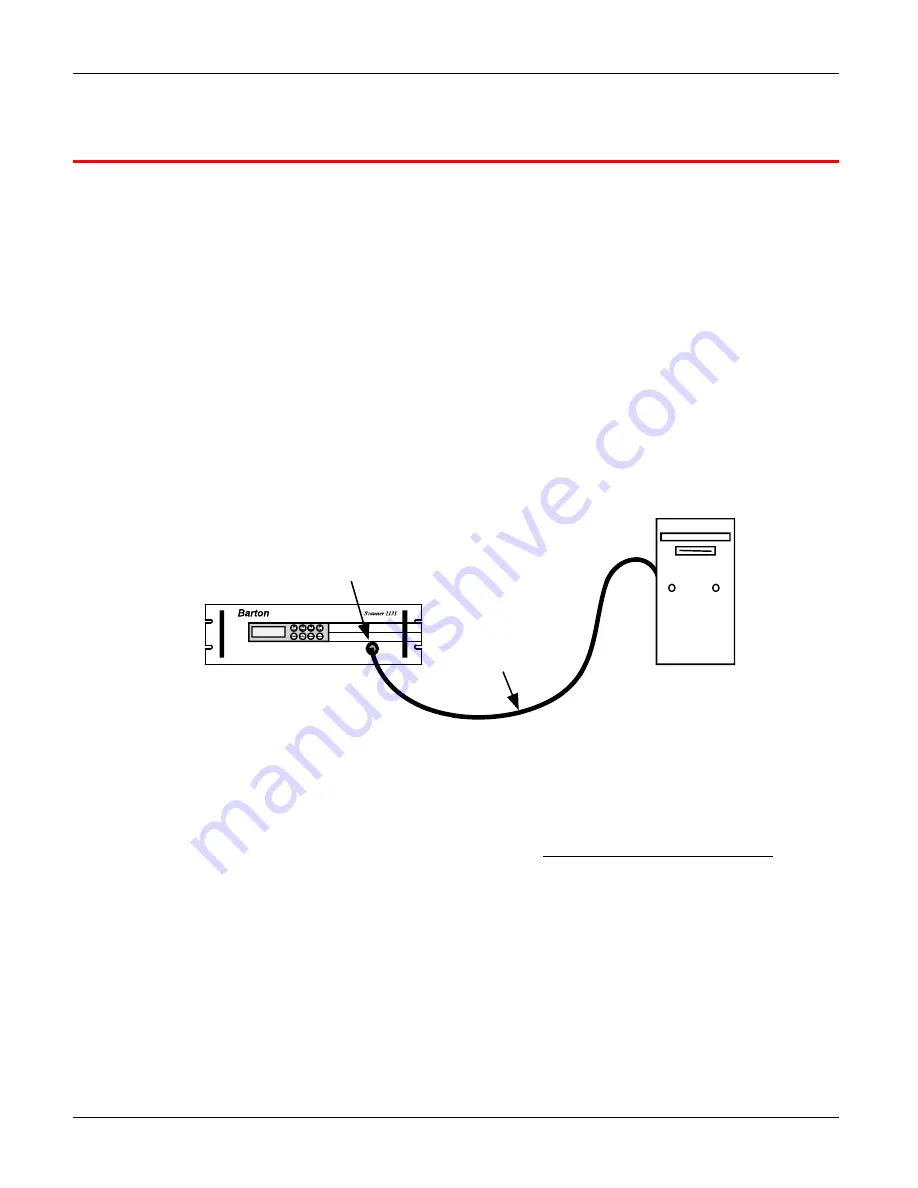
Connect the PC to the Scanner 1141’s console port (Figure E.1).
PC
Scanner Cable
Console Port
Figure E.1—PC to console connection for flashing firmware
2.
Start ScanWin.
3.
Download all history, configuration and calibration data.
(HIGHLY RECOMMENDED)
4.
Exit ScanWin.
5.
With the
Power
switch (SW9) in the “ON” position, press and hold the Program Erase button (as
show in Figure E.2) on the main circuit board to erase the existing Scanner firmware.
6.
Move the
Power
switch (SW9) to the “OFF” position to “power down” the Scanner 1141.
7.
If the
Configuration Locking
switch (SW11) is installed, verify that it is UNLOCKED.
8.
Proceed to flash a new firmware version with WinsLoad or ScanFLASH.
Summary of Contents for NUFLO 1141C
Page 1: ...Manual No 30165009 Rev 01 NUFLOTM Scanner 1141 RTU Hardware User Manual ...
Page 28: ...Scanner 1141 Hardware User Manual 28 Figure 3 1 Scanner 1141 main circuit board ...
Page 66: ...Scanner 1141 Hardware User Manual 66 ...
Page 67: ...Chapter 6 Parts List and Order Code 67 Chapter 6 Parts List and Order Code Scanner 1141C ...
Page 68: ...Scanner 1141 Hardware User Manual 68 Scanner 1141L ...
Page 69: ...Chapter 6 Parts List and Order Code 69 Scanner 1141G ...
Page 91: ...Appendix A Specifications 91 Outline Dimensions Scanner 1141C ...
Page 92: ...Scanner 1141 Hardware User Manual 92 Scanner 1141L Front and Side Views ...
Page 94: ...Scanner 1141 Hardware User Manual 94 Scanner 1141G ...
Page 96: ...Scanner 1141 Hardware User Manual 96 Drawing 1 Installation ...
Page 97: ...Appendix B Control Drawings 97 Drawing 2 Power Supply ...
Page 98: ...Scanner 1141 Hardware User Manual 98 Drawing 3 Communications Serial Ports ...
Page 99: ...Appendix B Control Drawings 99 Drawing 4 Status Pulse Inputs Outputs ...
Page 100: ...Scanner 1141 Hardware User Manual 100 Drawing 5 RTD Inputs Analog Inputs Outputs ...
Page 101: ...Appendix B Control Drawings 101 Drawing 6 Analog Outputs ...
Page 102: ...Scanner 1141 Hardware User Manual 102 ...
Page 117: ...117 ...
Page 118: ...118 ...
Page 119: ......
Page 120: ......


