


SERIE
RODEO
21
10
11
1
2
C1
Ri
M
R2
R1
2
F1 F2 ES ES
TX RX GND 1 2 3 4 5 6 7
MF9011 - MF9111
MA7032
MA7012
BUSSOLA
MA7041
P.R.AP
AP/PARZ
T CA
V.RA LL.CH V/CH
V/A P
P.R.CH
F RENO V.RA LL.AP.
-
+
M
N
E
+
S
S
E
-
-
BATT.
+
24AC
24AC
F1
F
2
E
s
E
s
Connection
for electric lock
MA 7012
Connection for
function switch MA 7041
C Nc 1 0
A2 C1 A1
A C
+
_
Emergency Battery
+
_
12 V 1.2Ah
12 V 1.2Ah
Bridge connection
for set of batteries
10
11
1
2
C1
Ri
M
R2
R1
2
F1 F2 ES ES
TX RX GND 1 2 3 4 5 6 7
MF9011 - MF9111
MA7032
MA7012
BUSSOLA
MA7041
P.R.AP
AP/PARZ
T CA
V.RA LL.CH V/CH
V/A P
P.R.CH
F RE NO V.RA LL.AP.
-
+
M
N
E
+
S
S
E
-
-
BATT.
+
24AC
24AC
C Nc 1 0
A2 C1 A1
A C
+
_
+
_
12 V 1.2Ah
12 V 1.2Ah
F1
F
2
E
s
E
s
Outer Radar
(2-R1)
Central Radar
or middle
(2-Ri)
Inner Radar
(2-R2)
MF9011-9111
MA7032
TX
RX GND
TX
RX GND
CONTROL
PANEL
(
MASTER
)
CONTROL
PANEL
(
SLAVE
)
BUSSOLA
1 2 3 4 5 6 7
ENTRY
EXIT
CLOSED
EMERGENCY
SELECTION
Cancelli Automatici
BUSSOLA
Connection
for electric lock
MA 7012
MF9011-9111
MA7032
Bridge connection
for set of batteries
Emergency Battery
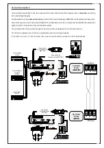
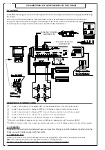
Connections required
Connect the accessories to the two panels and to each other using the compass clamp (bussola) according
to the illustrated diagram.
Set dip switch 6 on the outer automation system to ON, which will assign MASTER control status to that system.
All control sensors and function switch MA7041 (if installed) must be connected to the MASTER automation
system, which controls the other automation system.
The photoelectric cells and the anti-panic device must be independent on both automations.
The trimmer adjustments on the two automation system act independently.
If contacts 1-2 and 2-C1 are not used, they must be connected by jumpers on both automations.


