background image

P

age 

3

 - Manual 

FA01384-EN

  - 03/2021 - © C

AME S.p.A. - The contents of this manual may be changed at any time and without notice. - T

ranslation of the o

riginal instructions

GENERAL PRECAUTIONS FOR INSTALLERS

 Important safety instructions.

 Please follow all of these instructions. Improper installation may cause serious bodily harm.

 Before continuing, please also read the general precautions for users.

Only use this product for its intended purpose. Any other use is hazardous. • The manufacturer cannot be held liable for 
any damage caused by improper, unreasonable or erroneous use. • This product is defined by the Machinery Directive 
(2006/42/EC) as partly completed machinery. • Partly completed machinery means an assembly which is almost 
machinery but which cannot in itself perform a specific application. • Partly completed machinery is only intended to be 
incorporated into or assembled with other machinery or other partly completed machinery or equipment thereby forming 
machinery to which the Machinery Directive (2006/42/EC) applies. • The final installation must comply with the Machinery 
Directive (2006/42/EC) and the European reference standards in force. • The manufacturer declines any liability for using 
non-original products, which would also void the warranty. • All operations indicated in this manual must be carried out 
exclusively by skilled and qualified personnel and in full compliance with the regulations in force. • The device must be 
installed, wired, connected and tested according to good professional practice, in compliance with the standards and 
laws in force. • Make sure the mains power supply is disconnected during all installation procedures. • Check that the 
temperature ranges given are suitable for the installation site. • Make sure that opening the automatic barrier does not 
constitute a hazard. • Do not install on slopes i.e. any surfaces that are not perfectly level. • Do not install the operator on 
surfaces that could yield and bend. If necessary, add suitable reinforcements to the anchoring points. • Make sure that 
no direct jets of water can wet the product at the installation site (sprinklers, water cleaners, etc.). • Make sure you have 
set up a suitable dual-pole cut-off device along the power supply that is compliant with the installation rules. It should 
completely cut off the power supply according to category III surcharge conditions. • Demarcate the entire site properly 
to prevent unauthorised personnel from entering, especially minors. • In case of manual handling, have one person for 
every 20 kg that needs hoisting; for non-manual handling, use proper hoisting equipment in safe conditions. • When the 
operator is being fixed in place, it may be unstable and overturn. Be careful and do not lean on it until it is fully fastened 
in place. • Use suitable protection to prevent any mechanical hazards due to persons loitering within the operating range 
of the operator. • The electrical cables must pass through special pipes, ducts and cable glands in order to guarantee 
adequate protection against mechanical damage. • Make sure that the moving mechanical parts are suitably far away 
from the wiring. • The electrical cables must not touch any parts that may overheat during use (such as the motor and 
transformer). • All fixed controls must be clearly visible after installation, in a position that allows the guided part to be 
directly visible, but far away from moving parts. In the case of a hold-to-run control, this must be installed at a minimum 
height of 1.5 m from the ground and must not be accessible to the public. • If the passage is wider than 3 m, you must 
use a fixed support for the boom. • If not already present, apply a permanent tag that describes how to use the manual 
release mechanism close to it. • Make sure that the operator has been properly adjusted and that the safety and protection 
devices and the manual release are working properly. • Before handing over to the final user, check that the system 
complies with the harmonised standards and the essential requirements of the Machinery Directive (2006/42/EC). • Any 
residual risks must be indicated clearly with proper signage affixed in visible areas, and explained to end users. • Put the 
machine’s ID plate in a visible place when the installation is complete. • If the power supply cable is damaged, it must 
be immediately replaced by the manufacturer or by an authorised technical assistance centre, or in any case, by qualified 
staff, to prevent any risk. • Keep this manual inside the technical folder along with the manuals of all the other devices 
used for your automation system. • Make sure to hand over to the end user all the operating manuals of the products that 
make up the final machinery.

Summary of Contents for GGT80AGS

Page 1: ...Automatic road barriers GGT80AGS GGT80RGS GGT80ACS GGT80AX4 GGT80AX6 INSTALLATION MANUAL FA01384 EN EN English...

Page 2: ...the result of an accident or installation error In these cases the tensioned springs no longer guarantee that the boom is balanced The boom may suddenly rotate when being released Manual release may...

Page 3: ...th the installation rules It should completely cut off the power supply according to category III surcharge conditions Demarcate the entire site properly to prevent unauthorised personnel from enterin...

Page 4: ...uidelines DISPOSING OF THE PACKAGING The packaging materials cardboard plastic etc can be disposed of easily as solid urban waste separated for recycling Before dismantling and disposing of the produc...

Page 5: ...ainted galvanised steel cabinet accessories available Balance springs included Intended use Ideal solution for apartment blocks and industrial applications Any installation and or use other than that...

Page 6: ...ing cover 6 Photocell holes 7 Lock for release 8 Cabinet 9 Inspection hatch 10 Inspection hatch lock 11 Control panel 12 Safety microswitch with cover open 13 Mechanical stop for the boom adjustment 1...

Page 7: ...inal board associated with the RSE_2 connector for CRP connection IO 485 card or Modbus RTU interface 13 Terminal board for connecting the electric lock 14 Terminal board for connecting the safety mic...

Page 8: ...an indoor environment use cables with properties at least equivalent to those of type H05VV F designation to 60227 IEC 53 If the cable lengths differ from those specified in the table define the cable...

Page 9: ...ened in place Preliminary operations If the flooring does not allow the device to be fastened in a solid and stable way lay a cement slab Dig a hole for the foundation frame Set up the corrugated tube...

Page 10: ...otice Translation of the original instructions Fill the hole with soil around the concrete block Remove the nuts from the screws Thread the electrical cables into the tubes so that they protrude by ab...

Page 11: ...Page 11 Manual FA01384 EN 03 2021 CAME S p A The contents of this manual may be changed at any time and without notice Translation of the original instructions Changing the boom opening direction...

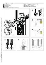
Page 12: ...l may be changed at any time and without notice Translation of the original instructions Boom installation Insert the reinforcement inside the boom First install the LED strip where applicable ONLY TH...

Page 13: ...s to the same size as the boom slot minus 10 millimetres 2 Insert the slot cover profiles into the grooves on both sides of the boom 3 Insert the anti impact rubber profile into the groove 4 Cut off t...

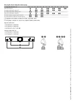
Page 14: ...h LED strip and full height skirt A A A A B B B B Boom with LED strip and swing rest A B A A A A A A A A Boom with LED strip single skirt and swing rest A A A A A A Boom with LED strip full height ski...

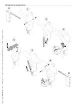
Page 15: ...riginal instructions Assembling the balance spring 1 Release the gearmotor 2 Position the boom vertically 3 Lock the gearmotor 4 5 6 Assemble the anchoring pin and fix it on the lever arm 7 Tighten th...

Page 16: ...otor 2 Manually turn the spring to increase or reduce the traction The boom should stabilise at 45 Where there are two springs carry out the procedure on both springs at the same time 3 Fasten the loc...

Page 17: ...with mechanical limit switches Check that the boom is parallel to the road surface when it is in the closed position and at about 89 when it is in the open position Correct the boom s horizontal posi...

Page 18: ...time and without notice Translation of the original instructions Correct the boom s vertical position Release the gearmotor Open the inspection hatch 1 Turn the mechanical stop until you reach the des...

Page 19: ...isconnected during all installation procedures Before working on the control panel disconnect the mains power supply and remove the batteries if any Connecting to the electrical network F Line fuse L...

Page 20: ...address on each device the function of each accessory can be configured on the control panel This method allows you to configure the set up immediately without having to do so later and intervene dire...

Page 21: ...2 Control device NO contact OPEN ONLY function When the HOLD TO RUN function is active the control device must be connected during OPENING 3 Control device NO contact PARTIAL OPENING function The cont...

Page 22: ...If the red LEDs are flashing quickly the inspection hatch is open the gearmotor is released or the boom has dropped away 10 11 E1 TS 1 2 3 3P 4 5 7 2 CX CY CZ R G 1 3 Safety devices Connect the safet...

Page 23: ...pairs can be connected See function F5 Safety devices test 10 11 E1 TS 1 2 3 3P 4 5 7 2 CX CY CZ 10 2 TX C NC TX 2 RX TX 10 11 E1 TS 1 2 3 3P 4 5 7 2 CX CY CZ 10 2 TX C NC TX 2 RX TX DXR DLX photocell...

Page 24: ...nd qualified staff may perform this operation Check the warning and safety devices are working properly Make sure that there are no obstacles in the way Power up and proceed with the operations indica...

Page 25: ...osure at the travel end during opening C7 Reopen while closing sensitive edges C9 Immediate closure at the travel end during opening with obstacle standby during closure C10 Immediate closure during o...

Page 26: ...safety devices detect an obstacle The function activates with closed boom open boom or after a complete stop F9 Obstacle with motor stopped OFF Default ON Open warning light Barrier status warning Dev...

Page 27: ...safety devices are triggered when an obstacle is detected after a complete stop during a power outage or if there is an error F19 Automatic closure OFF Default From 1 to 180 seconds Pre flashing time...

Page 28: ...ions from the memory device memory roll or USB key The function is displayed only when a USB stick is inserted into the USB port or when a memory roll card is inserted into the control board F51 Read...

Page 29: ...t while opening or closing the FCA CM1 or FCC CM2 contact closes and remains closed 3 Custom The FCA CM1 contact is closed with the boom in the open travel end position and during the opening manoeuvr...

Page 30: ...user Remove one of the registered users U2 Remove user OFF Default ON Use the arrows to choose the number associated with the user you want to remove No 1 250 Alternatively the control device associa...

Page 31: ...anoeuvre counter View the number of manoeuvres performed by the operator 1 1000 manoeuvres A5 Manoeuvre counter tot total manoeuvres PAr partial manoeuvres FW version Display the firmware version numb...

Page 32: ...e standby during closure NO contact C13 Reopen while closing with immediate stop once the obstruction has been removed even if the gate is not in motion C23 Open command C24 Close command Import expor...

Page 33: ...Page 33 Manual FA01384 EN 03 2021 CAME S p A The contents of this manual may be changed at any time and without notice Translation of the original instructions FINAL OPERATIONS...

Page 34: ...essories must be connected to the control board which will be set as the MASTER RSE A B GND S1 GND A B GND UTP CAT 5 max 1000 m RSE A B GND S1 GND A B GND Programming All programming operations descri...

Page 35: ...ector Connect up the electrics for the devices and accessories For information on connecting the electrics for the devices and accessories please see the ELECTRICAL CONNECTIONS section The control and...

Page 36: ...21 CAME S p A The contents of this manual may be changed at any time and without notice Translation of the original instructions 2 ONLY OPEN command 2 3 on barrier B 3 OPEN CLOSE command 2 7 on barrie...

Page 37: ...t catalogue If the barrier with an articulated joint is used check that the moving parts of the joint are in good condition Replace them if necessary Every 250 000 cycles and in any case every 6 month...

Page 38: ...1 Calibration error E3 Encoder failure error E4 Service test failure error E7 Operating time error E8 Open release hatch error E9 Obstacle detected during closing E10 Obstacle detected during opening...

Page 39: ...Page 39 Manual FA01384 EN 03 2021 CAME S p A The contents of this manual may be changed at any time and without notice Translation of the original instructions...

Page 40: ...AME S p A The contents of this manual may be changed at any time and without notice Translation of the original instructions CAME S p A Via Martiri della Libert 15 31030 Dosson di Casier Treviso Italy...

Reviews: