background image

Page 

32

 - Manual 

FA01625-EN

  - 02/2023 - © C

AME S.p.A. - The contents of this manual may be changed at any time and without notice. - T

ranslation of the o

riginal instructions

CAME S.p.A.

Via Martiri della Libertà, 15
31030 Dosson di Casier
Treviso – Italy
Tel. (+39) 0422 4940
Fax (+39) 0422 4941

Summary of Contents for GARD G6000

Page 1: ...Automatic road barriers G6000 G6001 G6001 316 G6000X G6000Y G6010 G6010X INSTALLATION MANUAL FA01625 EN EN English...

Page 2: ...m is no longer intact as the result of an accident or installation error In these cases the tensioned springs no longer guarantee that the boom is balanced The boom may suddenly rotate when being rele...

Page 3: ...20 kg that needs hoisting for non manual handling use proper hoisting equipment in safe conditions When the operator is being fixed in place it may be unstable and overturn Be careful and do not lean...

Page 4: ...uidelines DISPOSING OF THE PACKAGING The packaging materials cardboard plastic etc can be disposed of easily as solid urban waste separated for recycling Before dismantling and disposing of the produc...

Page 5: ...C 230 AC 230 AC 230 AC 120 AC 120 AC Motor power supply V 24 DC 24 DC 24 DC 24 DC 24 DC 24 DC 24 DC Power W 300 300 300 300 300 300 300 Current draw A 15 Max 15 Max 15 Max 15 Max 15 Max 15 Max 15 Max...

Page 6: ...and without notice Translation of the original instructions Description of parts Barrier 1 Boom attachment 2 Boom anchoring plate 3 Lock for release 4 Cabinet 5 Inspection hatch 6 Microswitch support...

Page 7: ...ecting the transponder selector switch 5 Display 6 Accessories fuse 7 Control board fuse 8 Terminal board for connecting the transformer 9 Terminal board for connecting the transformer thermal cut off...

Page 8: ...a use RG58 cable up to 5 m For installation in an outdoor environment use cables with properties at least equivalent to those of type H05RN F with designation 60245 IEC 57 For installation in an indoo...

Page 9: ...ed in place Preliminary operations If the flooring does not allow the device to be fastened in a solid and stable way lay a cement slab Dig a hole for the foundation frame Set up the corrugated tubes...

Page 10: ...nged at any time and without notice Translation of the original instructions Fill the hole with soil around the concrete block Remove the nuts from the screws Insert the electrical cables into the tub...

Page 11: ...ice Translation of the original instructions Changing the boom opening direction The barrier is set up for installation on the left If the boom has already been assembled lift it up to a vertical posi...

Page 12: ...armotor arm 90 Turn the transmission lever 90 and fix it in place again using the screw Turn it anticlockwise to change the opening from left to right Turn it clockwise to change the opening from righ...

Page 13: ...gs 50 mm fitted in the holes marked B Passage width clearance m 3 4 4 5 5 6 6 6 5 Boom A A B A B Boom with warning lights 001G0460 A B A B Boom with warning lights and skirt 001G0465 B A B B B Boom wi...

Page 14: ...m 1 Release the gearmotor 2 Loosen the clamping nut on the rod 3 Manually turn the spring to increase or reduce the traction The boom should stabilise at 45 4 Fasten the locknut Position the boom vert...

Page 15: ...th mechanical limit switches Check that the boom is parallel to the road surface when it is in the closed position and at about 89 when it is in the open position Correct the boom s horizontal positio...

Page 16: ...and without notice Translation of the original instructions Correct the boom s vertical position Release the gearmotor Open the inspection hatch 1 Turn the transmission lever until the boom is in the...

Page 17: ...nical parts are suitably far away from the wiring Power supply Make sure the mains power supply is disconnected during all installation procedures Before working on the control panel disconnect the ma...

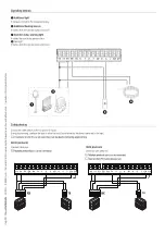
Page 18: ...s the boom and excludes automatic closing Use a control device to resume movement If the contact is not used it must be deactivated during programming 2 Control device NO contact OPEN ONLY function Wh...

Page 19: ...and closes 10 11 E1 E6 Rx Tx 1 2 3 3P 4 5 7 CY CX 1 3 Safety devices Connect the safety devices to the CX and or CY inputs During programming configure the type of action that must be performed by th...

Page 20: ...nction F60 Sleep Mode DIR DELTA S photocells Standard connection Multiple photocell pairs can be connected Connection with safety test Multiple photocell pairs can be connected See function F5 Safety...

Page 21: ...be connected DXR DLX photocells Connection with safety test Multiple photocell pairs can be connected See function F5 Safety devices test RX TX 10 11 OUT 10 11 SY 10 11 E1 E6 Rx Tx 1 2 3 3P 4 5 7 CY...

Page 22: ...t manoeuvre is always to open the gate Wait for the manoeuvre to be completed Press the ESC button or STOP button immediately in the event of any faults malfunctions strange noises or vibrations or un...

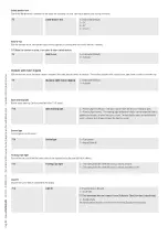
Page 23: ...Open warning light Barrier status warning Device connected to the 10 5 output F10 Open warning light 0 Warning light on default The light stays on when the boom is moving or open 1 Warning light flash...

Page 24: ...e during opening and closing F22 Operating time 5 to 120 seconds default 20 seconds Courtesy time Set the lighting device operation time F25 Courtesy time 60 to 180 seconds Default 180 seconds Opening...

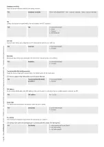
Page 25: ...ry roll or USB key F51 Read data 0 Deactivated Default 1 Activated Transferring MASTER SLAVE parameters Enable the sharing of parameters programmed on the Master barrier with the Slave barrier This on...

Page 26: ...mmand opens the Master barrier Choose the function to be assigned to the user Press ENTER to confirm You will be asked to enter your user code Send the code from the control device Repeat the procedur...

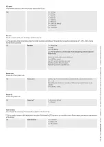
Page 27: ...neuvers FW version Display the firmware version number H1 FW version Import export data 1 Insert the MEMORY ROLL card into the corresponding connector on the control board 2 Press the Enter button to...

Page 28: ...RSE connector Connect up the electrics for the devices and accessories For information on connecting the electrics for the devices and accessories please see the ELECTRICAL CONNECTIONS section The dev...

Page 29: ...ON The first barrier opens the vehicle passes the first barrier closes the second barrier opens the vehicle passes and the second barrier closes Electrical connections Connect the two electronic board...

Page 30: ...ction F49 Press ENTER to confirm Select 2 Select function F52 Select 1 Saving users All save user operations must be performed only on the control board set as the MASTER For user storage operations s...

Page 31: ...rect installation and adjustments please see the product installation manual For information on choosing products and accessories please see our product catalogue If the barrier with an articulated jo...

Page 32: ...AME S p A The contents of this manual may be changed at any time and without notice Translation of the original instructions CAME S p A Via Martiri della Libert 15 31030 Dosson di Casier Treviso Italy...

Reviews: