


Pa
g.
5
- M
an
u
al
c
od
e:
11
9
D
U
3
2
E
N
11
9
D
U
3
2
E
N
ve
r.
2
2
0
1/
2
0
14 © C
A
M
E S
.p.
A
. - T
h
e d
ata a
n
d i
nf
or
m
ati
on r
ep
orte
d i
n th
is
in
sta
lla
tio
n m
an
u
al
a
re s
u
sc
ep
tib
le to c
h
an
g
e at a
ny ti
m
e a
n
d w
ith
ou
t o
b
lig
ati
on
o
n C
A
M
E S
.p.
A
. to n
otify u
se
rs.
ENGLISH
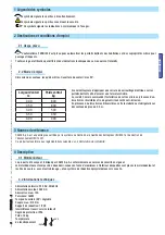
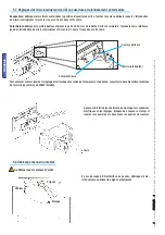
5.2 Tools and materials
Make sure you have all the tools and materials you will need for the installation at hand to work in total safety and compliance
with the current standards and regulations. The following figure illustrates the minimum equipment needed by the installer.
5.3 Cable list and minimum thickness
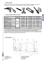
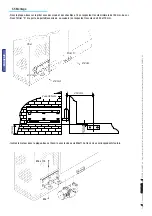
5.4 Standard installation
5 - Flashing light
6 - Selector switch
7 - Photocells
8 - Electric lock
1 - Operator
2 - Control panel
3 - Radio receiver
4 - Antenna
Connection
Type of
cable
Cable length
1 < 10 m
Cable length
10 < 20 m
Cable length
20 < 30 m
230 V control panel power supply
FROR CEI
20-22
CEI EN
50267-2-1
3G x 1.5 mm
2
3G x 1.5 mm
2
3G x 2.5 mm
2
24 V motor power supply
2G x 1.5 mm
2
2G x 1.5 mm
2
2G x 2.5 mm
2
Flashing light
2 x 1.5 mm
2
2 x 1.5 mm
2
2 x 1.5 mm
2
Photocell transmitters
2 x 0.5 mm
2
2 x 0.5 mm
2
2 x 0.5 mm
2
Photocell receivers
4 x 1.5 mm
2
4 x 1.5 mm
2
4 x 1.5 mm
2
Accessories power supply
2 x 0.5 mm
2
2 x 0.5 mm
2
2 x 1 mm
2
Command and safety devices
2 x 0.5 mm
2
2 x 0.5 mm
2
2 x 0.5 mm
2
Antenna connection
RG58
max. 10 m
N.B.: If the cable length differs from that specified in the table, then you must determine the proper cable diameter in the basis of
the actual power drawn by the connected devices and depending on the standards specified in CEI EN 60204-1.
For connections that require several, sequential loads, the sizes given on the table must be re-evaluated based on actual power
draw and distances. When connecting products that are not specified in this manual, please follow the documentation provided
with said products.