background image

25

Antenna

INSTALL AND PROGRAM THE 

S 2.0™ RADIO CARD

 Connect  the  antenna.

 Disconnect all power to the operator including the batteries.

 Insert the S 2.0™ radio card into the slot on the electronic card. 

Connect power.


NOTE:

 The electronic card picks up the S 2.0™ radio card when the 

operator is powered up.

 Press the button on the S 2.0™ radio card (the LED will light). 

 Press the button on the remote control (the LED on the radio card will go out if 

programming is successful).

7

   Press and hold the PROG button on the electronic card (the LED will flash).

8

   Press the button on the remote control again (the LED on the electronic card 

will go out).

To program additional remote controls follow steps 5 and 6 above only.

INSTALL AND PROGRAM THE S 2.0™ RADIO CARD

PROGRAMMING

M N

L2T

L1T

0

17

26

10 11 E1 1

2 3P 5

7

2 C1 C3 C7 C8 TS

+ E

-

FC FA

F

L NE FUSE

230V=1 6A F

120V=3 15A F

MOTOR FUSE

BX243=8A F

BX246=10A F

ACCESSORIES

FUSE 

1 6A F

C  BOARD

FUSE

1A F

+

 RUN S  

- +

 SLOW S  

- +

 RU    


ZN5

CONTROL BOARD

PWR

1

C1

C3

ON

2

1

3

4

5

6

7

8

9 10

ROG

M N

L2T

L1T

L N

0

17

26

10 11 E1 1

2 3P 5

7

2 C1 C3 C7 C8 TS

+ E

-

FC FA

F

C7
C8

ZN5U

LED

PROG Button

Remote 

Control

S 2.0™ Card

ERASE THE S 2.0™ RADIO CARD MEMORY

 Press and hold the button on the S 2.0™ radio card until the LED goes 

out (approximately 6 seconds). The memory is now erased.

NOTICE: This device complies with Part 15 of the FCC rules and Industry Canada (IC) licence-exempt RSS-210. Operation is subject to the 

following two conditions: (1) this device may not cause harmful interference, and (2) this device must accept any interference received, 

including interference that may cause undesired operation.

Any changes or modifications not expressly approved by the party responsible for compliance could void the user’s authority to operate the 

equipment.

This Class B digital apparatus complies with Canadian ICES-003.

Summary of Contents for BX243C

Page 1: ... PRODUCT IS TO BE INSTALLED AND SERVICED BY A TRAINED GATE SYSTEMS TECHNICIAN ONLY Visit www liftmaster com to locate a professional installing dealer in your area This model is for use on vehicular passage gates ONLY and not intended for use on pedestrian passage gates This model is intended for use in Class I vehicular slide gate applications ...

Page 2: ...ATION 3 GATE CONSTRUCTION INFORMATION 4 REQUIRED ENTRAPMENT PROTECTION DEVICES 5 IMPORTANT SAFETY INFORMATION 6 INTRODUCTION 7 OPERATOR SPECIFICATIONS 7 CARTON INVENTORY 7 OPERATOR DIMENSIONS 7 PREPARATION 8 TOOLS AND MATERIALS 8 WIRING CHART 8 SITE PREPARATION 8 INSTALLATION 9 PREPARE AND INSTALL THE MOUNTING PLATE 9 PREPARE AND INSTALL THE MOUNTING PLATE 10 INSTALL THE CHAIN MODEL BX243C ONLY 11...

Page 3: ... protection and one independent secondary means of entrapment protection Both primary and secondary entrapment protection methods must be designed arranged or configured to protect against entrapments in both the open and close directions of gate travel For Example For a gate system that is installed on a single family residence UL325 Class I you must provide the following As your primary type of ...

Page 4: ...n of the gate operator 8 Controls intended for user activation must be located at least 6 feet 1 8 m away from any moving part of the gate and where the user is prevented from reaching over under around or through the gate to operate the controls Outdoor or easily accessible controls shall have a security feature to prevent unauthorized use 9 The Stop and or Reset if provided separately must be lo...

Page 5: ...stalled in accordance with ASTM F2200 Standard Specification for Automated Vehicular Gate Construction For a copy contact ASTM directly at 610 832 9585 or www astm org 3 1 3 A gap measured in the horizontal plane parallel to the roadway between a fixed stationary object nearest the roadway such as a gate support post and the gate frame when the gate is in either the fully open position or the full...

Page 6: ...obstruction is cleared Use model G65MGO20 G65MGR20 or G65MGS20 REQUIRED ENTRAPMENT PROTECTION DEVICES SAFETY REQUIRED ENTRAPMENT PROTECTION DEVICES An entrapment zone is every location or point of contact where a person can become entrapped between a moving gate and a stationary object All gate operator systems REQUIRE two independent entrapment protection systems for each entrapment zone This ope...

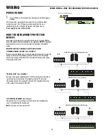
Page 7: ...d connected in accordance with national and local electrical codes After ANY adjustments are made the safety reversal system MUST be tested Gate MUST reverse on contact with a rigid object ALL electrical connections MUST be made by a qualified individual DO NOT install ANY wiring or attempt to run the operator without consulting the wiring diagram We recommend that you install an edge sensor BEFOR...

Page 8: ...in AC Supply 120 Vac 50 60Hz Input Rating 170 Watts at 120Vac Main Supply Motor 7 Amps at 24Vdc Accessory Power 24 Vac 1 5A Full Cycle Time 7 87 inches second Maximum Gate Weight Length 660 lbs 28 foot Daily Cycle Rate AC power 25 cycles day Ambient Temperature 20 C to 55 C 4 F to 131 F Fuse Protection Motor 8A F 250 Vac 6x32mm Fuse Protection Control Board 1A F 250 Vac 5x20mm Fuse Protection AC L...

Page 9: ...cts more than 1 32 3 mm apart and independent sectioned off power supply 7 Check that any connections inside the container that provide continuity to the safety circuit are fitted with additional insulation compared to other internal live parts 8 Make sure you have suitable tubing and conduits for the electrical cables to pass through and be protected against mechanical damage SITE PREPARATION Dri...

Page 10: ... be installed 3 Prepare a form box larger than the mounting plate and insert the form box in the hole Figure 2 The form box should be 1 3 4 50 mm above the ground Figure 2 4 Insert an iron grid inside the form to reinforce the concrete Figure 2 5 Insert the bolts into the holes of the mounting plate and secure with nuts and washers supplied Figure 3 6 Extend the preformed tabs on the mounting plat...

Page 11: ...llow the concrete to cure Figure 6 10 Remove the form box Figure 7 11 Fill the hole around the concrete form with soil Figure 7 12 Remove the nuts and washers from the bolts Figure 7 The mounting plate must be clean perfectly level and with the bolt threads completely above the surface For model BX243C Chain proceed to page 11 For model BX243R proceed to page 14 1 97 2 17 PREPARE AND INSTALL THE M...

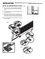
Page 12: ...ckets with bolts and washers Figure 2 3 Attach the chain to the gate brackets with hardware supplied Figure 2 If the chain is too long cut off the excess If necessary fasten the extension bracket to the back side of the gate to allow the gate to open and close fully Figure 3 4 Adjust the chain tension by turning the outer nut Tighten the inner nut to secure the adjustment Figure 4 4 5 16 110 mm 1 ...

Page 13: ... the rubber plug to allow the wires to be threaded through Figure 1A 3 Remove the four screws that secure the pulley cover to the operator Figure 1B 4 Run the electrical wires through the conduit allow at least 15 3 4 inches 400 mm to protrude Figure 2A 5 Position the operator over the mounting plate and pull electrical wires through the rubber plugs Lower operator on to the mounting plate Align t...

Page 14: ...lots for horizontal adjustments Figure 1A 7 Once adjustments are complete secure the operator with the bolts and nuts Figure 1B 8 Re attach the pulley cover with four screws Figure 1C 9 Secure the cover with a screw on each side Figure 1D INSTALLATION INSTALL THE OPERATOR MODEL BX243C ONLY FIGURE 1A FIGURE 1B FIGURE 1C FIGURE 1D ...

Page 15: ...int Secure the rack pieces with two C clamps Figure 1B 4 Weld the rack to the gate along its entire length Figure 1C 5 Open and close the gate manually and register the rack to pinion distance using the levelling feet for vertical adjustment and the slotted holes for horizontal adjustment Figure 2 6 Secure the operator using the nuts and washers Figure 3 7 Secure the cover with a screw on each sid...

Page 16: ...e page 16 for a wiring diagram OPEN LIMIT 1 Manually release the operator and fully open the gate 2 Loosen the screw on the white cam 3 Slide the white cam clockwise until it makes contact with the limit switch 4 Tighten the screw on the white cam to lock the adjustment CLOSE LIMIT 1 Manually release the operator and fully close the gate 2 Loosen the screw on the red cam 3 Slide the red cam counte...

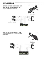
Page 17: ...hange to a right hand installation reverse the wiring for the motor M N and limit switches FA FC COM NC NC COM Red Orange White Green Left handed factory default 24V AC motor with encoder Close limit switch Open limit switch Orange White Brown Green Red COM NC NC COM White Red Green Red Right handed 24V AC motor with encoder INSTALLATION DETERMINE OPENING DIRECTION OF GATE LEFT HAND RIGHT HAND ...

Page 18: ...Power Supply Terminals 2 Limit Switch Terminals 3 Motor Terminals 4 Encoder Terminals 5 Accessory Fuse 6 Card Fuse 7 Program Button 8 Radio Alert LED 9 120V Power LED 10 Control and Signalling LED Group 11 Function Selector DIP Switch 12 Security 2 0 radio card connector 13 Antenna Terminal 14 Accessory and Command Device Terminals 15 Motor Fuse 16 Line Fuse 17 Operational Settings 18 Transformer ...

Page 19: ...PHOTOELECTRIC SENSOR CONFIGURATIONS OPENING DURING CLOSING N C CONTACT If contact is opened while the gate is closing the gate reverses direction To select this function set the number 9 functionality switch to OFF refer to the Functionality Switches chart on page 22 Default is OFF To disable this function set the number 9 functionality switch to ON PARTIAL STOP N C CONTACT Gate stops if moving an...

Page 20: ... used short circuit contact 2 C7 CLOSE WHILE OPENING N C Contact This input functions to reverse the gate to the close limit when the edge is activated during the opening cycle NOTE If not used short circuit contact 2 C8 C NO NC 0 43 Two wire normally open edge Connect power to the operator Wireless Communicator Transmitter 24V C PWR Relay Receiver C NO NC 0 43 Two wire normally open edge Wireless...

Page 21: ...g the button or turning the key the gate reverses direction or stops depending on the functionality switch settings WARNING DEVICES Open gate indicator light Signals that gate is open turns off when the gate is closed Contact power 24V A C 25W maximum Socket rating 24V 3W maximum NOTE If the operator detects an obstacle in the same direction twice while running the electronic card activates the wa...

Page 22: ...s the card is properly powered up Radio Alert Red Red LED Normally off The red Radio Alert LED flashes or turns on indicating a signal from a remote control OPERATIONAL SETTINGS SETTING FUNCTION A C T Automatic Close Timer The ACT is also referred to as Timer to Close The ACT can be set to automatically close the gate after a specified time period If the ACT is set to the OFF position then the gat...

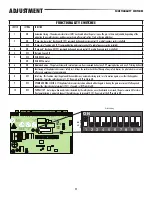
Page 23: ...h 2 7 command button and remote control if a radio frequency card is installed 4 OFF Not used Leave OFF 5 OFF With BX 243 motor ON With BX 246 motor 6 ON Maintained action The gate activates with constant pressure from command button one 2 3P opening button and one 2 7 closing button 7 ON Functioning of the photoelectric sensors safety test Allows the card to check the efficiency of any safety dev...

Page 24: ...els any commands from the remote control or push button 1 Electrical connection to operate the photoelectric sensors safety test Connect the transmitter and receiver as shown in the diagram Set DIP switch 7 to ON to activate the test 2 When the safety test function is activated the N C contacts If unused are to be excluded on their relative DIP switches see Functionality Switches 48 48 0 43 0 43 D...

Page 25: ...ionality switch to OFF to save the settings to avoid resetting the adjustments after power outage RUN S OW S RUN ON 2 1 3 4 5 6 7 8 9 10 OG ON 2 1 3 4 5 6 7 8 9 10 Functionality Switch 6 in ON PROG LED on Functionality Switch 6 in OFF FIGURE 1 FIGURE 2 FIGURE 3 FIGURE 4 M N L2T L T 0 17 26 10 11 E1 1 2 3P 5 7 2 C1 C3 C7 C8 TS E FC FA F LINE FUSE 230V 1 6A F 120V 3 15A F MOTOR FUSE BX243 8A F BX246...

Page 26: ...C1 C3 C7 C8 TS E FC FA F L NE FUSE 230V 1 6A F 120V 3 15A F MOTOR FUSE BX243 8A F BX246 10A F ACCESSORIES FUSE 1 6A F C BOARD FUSE 1A F RUN S SLOW S RU ZN5 CONTROL BOARD PWR 1 C1 C3 ON 2 1 3 4 5 6 7 8 9 10 ROG M N L2T L1T L N 0 17 26 10 11 E1 1 2 3P 5 7 2 C1 C3 C7 C8 TS E FC FA F C7 C8 ZN5U LED PROG Button Remote Control Security 2 0 Card ERASE THE SECURITY 2 0 RADIO CARD MEMORY 1 Press and hold t...

Page 27: ...of the operator s rating Disconnect all power to the operator before servicing ALWAYS disconnect the batteries to service the operator MAINTENANCE CHART DESCRIPTION TASK CHECK AT LEAST ONCE EVERY MONTH 6 MONTHS Entrapment Protection Devices Check and test for proper operation X Warning Signs Make sure they are present X Manual Disconnect Check and test for proper operation X Drive Chain and Pulley...

Page 28: ..._______________________________________________________________________ __________________________________________________________________________________________ ______________________ Installer s stamp Operator name Date of job Technician s signature Requester s signature Job performed _________________________________________________________________________________ _____________________________...

Page 29: ...l not open Edge sensor triggered Call assistance The flasher does not work The bulb is burned out Call assistance DISPOSAL DISPOSAL OF PRODUCT Our products are made using different types of materials The majority of them aluminium plastic iron electric cables can be considered to be solid urban waste They may be recycled at authorised firms Other components electrical circuit board remote control ...

Page 30: ...ck Cylinder 119RIBX042 5 Release Door 119RIBX043 6 Motor 119RIBX046 7 Slow Shaft 119RIBX048 8 Support Tray for Electronic Card 119RIBX050 9 Gearmotor Crown 119RIBX052 10 Pinion 119RIBZ005 11 Worm Gear 119RIBZ007 12 Motor Flange and Gasket 119RIBZ017 13 Transformer 119RIR374 14 Electronic Card ZN5U 3199ZN5 NOT SHOWN Chain Drive Conversion Kit 119RIBX055 Security 2 0 Radio Card AF43CH ...

Page 31: ...r facilities by submitting a warranty claim and request for RGA with our customer service department Products shipped without an RGA number will not be accepted Replacements or repaired parts are covered by this warranty for the remainder of the thirty six 36 month warranty for the original product or six 6 months from the date of repair or replacement whichever is greater CAME will pay shipping c...

Page 32: ...01 36709C 2012 The Chamberlain Group Inc All Rights Reserved 845 Larch Avenue Elmhurst Illinois 60126 1196 ...

Page 33: ... PERSONNEL DÛMENT FORMÉ SUR LES SYSTÈMES DE BARRIÈRES Rendez visite à www liftMaster com pour localiser le revendeur installateur le plus proche de chez vous Ce modèle est pour utilisation sur les barrières de passage véhiculaire UNIQUEMENT et n est pas conçu pour utilisation sur les barrières de passage piétonnier Ce modèle est conçu pour utilisation dans les applications de barrière véhiculaire ...

Page 34: ...ENT SUR LA CONSTRUCTION DE LA BARRIÈRE 4 DISPOSITIFS DE PROTECTION CONTRE LE PIÉGEAGE EXIGÉS 5 RENSEIGNEMENTS DE SÉCURITÉ IMPORTANTS 6 INTRODUCTION 7 SPÉCIFICATIONS DU DISPOSITIF DE FERMETURE 7 INVENTAIRE DE L EMBALLAGE 7 DIMENSIONS DE L ACTIONNEUR 7 PRÉPARATION 8 OUTILS ET MATÉRIAUX 8 TABLEAU DE CÂBLAGE 8 PRÉPARATION DU SITE 8 INSTALLATION 9 PRÉPARER ET INSTALLER LA PLAQUE DE MONTAGE 9 PRÉPARER E...

Page 35: ...e indépendant de protection contre le piégeage Les deux méthodes de protection contre le piégeage primaire et secondaire doivent être conçues arrangées et configurées pour protéger contre le piégeage tant dans la direction ouverture que dans la direction fermeture du déplacement de la barrière Par exemple Pour un système de barrière qui est installé sur une résidence unifamiliale Classe I UL325 vo...

Page 36: ...l installation de l actionneur de barrière 8 Les contrôles prévus pour activation par l utilisateur doivent être situés a une distance éloignée d au moins six pieds 6 pi 1 8 m de toute partie de déplacement de la barrière et de plus doit être placé de façon tel pour empêcher l utilisateur d opérer les contrôles en passant par dessous en dessous autour ou au travers de la barrière Les contrôles don...

Page 37: ...u d un grillage pour qu une sphère d un diamètre de 102 mm 4 po ne puisse passer par toute ouverture située sur la barrière et sur la portion de la clôture adjacente qui la barrière recouvre lorsqu en position ouverte 3 1 3 Un espace mesuré dans le plan horizontal parallèle à la route entre un objet fixe stationnaire le plus près de la route comme un poteau de support de barrière et le cadre de la...

Page 38: ...dans cette direction tant que l obstruction ne sera pas enlevée Utilisation pour les modèles G65MG020 G65MGR20 ou G65MGS20 DISPOSITIFS DE PROTECTION CONTRE LE PIÉGEAGE EXIGÉS SÉCURITÉ DISPOSITIFS DE PROTECTION CONTRE LE PIÉGEAGE EXIGÉS Une zone de piégeage est tout endroit ou point de contact où une personne peut être piégée entre une barrière en mouvement et un objet stationnaire Tous les système...

Page 39: ...es Après avoir effectué quelque réglage que ce soit on DOIT faire l essai du système d inversion de sécurité La course de la barrière DOIT s inverser au contact d un objet rigide TOUTES les connexions électriques DOIVENT ÊTRE réalisées par un professionnel N installez PAS les câbles et N essayez PAS de faire fonctionner le dispositif de fermeture sans avoir pris connaissance du schéma de câblage N...

Page 40: ...coulissante Classifications de barrière CLASSE I Alimentation CA principale 120 Vca 50 60Hz Entrée nominale 170 W à 120 Vca Alimentation principale Moteur 7A à 24 Vcc Alimentation accessoire 24 Vca 1 5A Durée d un cycle complet 7 87 po seconde Poids longueur maximum de la barrière 660 lb 28 pi Cycle quotidien nominal alimentation CA 25 cycles jour Température ambiante 20 C à 55 C 4 F à 131 F Prote...

Page 41: ... LES RÉGLEMENTATIONS EXISTANTES La barrière doit être construite et installée en accordance avec les standards ASTFM F2200 Avant l installation effectuer les étapes suivantes 1 S assurer que la barrière est stable et que les roulettes sont en bonne condition et correctement graissées 2 Le support de terre doit être bien fixé au sol entièrement au dessus de la surface et libre de toute irrégularité...

Page 42: ...e la plaque de montage et insérer la boîte de forme dans le trou Figure 2 La boîte de forme devrait être à 50 mm 1 75 po au dessus du sol Figure 2 4 Insérer un grillage de fer à l intérieur de la forme pour renforcer le béton Figure 2 5 Insérer les boulons dans les trous de la plaque de montage et fixer les avec les écrous et les rondelles fournies Figure 3 6 Étendre les onglets préformés sur la p...

Page 43: ... du béton Figure 6 10 Retirer la boîte de forme Figure 7 11 Remplir le trou autour de la forme de béton avec de la terre Figure 7 12 Retirer les écrous et les rondelles des boulons Figure 7 La plaque de montage doit être propre parfaitement au niveau et les filets des boulons doivent se trouver en entier au dessus de la surface Pour le modèle BX243C Chaîne aller à la page 11 Pour le modèle BX243R ...

Page 44: ...et les rondelles Figure 2 3 Attacher la chaîne aux supports de barrière avec la quincaillerie fournie Figure 2 Si la chaîne est trop longue en couper l excès Si nécessaire fixer le support d extension au côté arrière de la barrière pour permettre à celle ci de s ouvrir et de se fermer en entier Figure 3 4 Ajuster la tension de la chaîne en tournant l écrou extérieur Serrer l écrou interne pour fix...

Page 45: ...aoutchouc afin de permettre de passer les fils à travers Figure 1A 3 Retirer les quatre vis qui fixent le couvercle de poulie à l actionneur Figure 1B 4 Passer les fils électriques à travers le conduit laisser dépasser d environ 400 mm 15 3 4 po Figure 2A 5 Positionner l actionneur par dessus la plaque de montage et tirer les fils électriques à travers les bouchons de caoutchouc Abaisser l actionn...

Page 46: ... les ajustements horizontaux Figure 1A 7 Lorsque les ajustements sont effectués fixer solidement l actionneur à l aide des boulons et des écrous Figure 1B 8 Rattacher le couvercle de poulie avec quatre vis Figure 1C 9 Fixer le couvercle avec une vis de chaque côté Figure 1D INSTALLATION INSTALLER L ACTIONNEUR MODÈLE BX243C SEULEMENT FIGURE 1A FIGURE 1B FIGURE 1C FIGURE 1D ...

Page 47: ...er les pièces de crémaillère avec deux brides en C Figure 1B 4 Souder le support à la barrière le long de sa longueur en entier Figure 1C 5 Ouvrir et fermer la barrière manuellement et enregistrer la distance entre le pignon et la crémaillère en utilisant le pied niveleur pour ajustement vertical et les trous ovales pour ajustement horizontal Figure 2 6 Fixer l actionneur à l aide des écrous et de...

Page 48: ...Dégager manuellement l actionneur et ouvrir la barrière en entier 2 Desserrer la vis sur la came blanche 3 Glisser la came blanche dans le sens horaire jusqu à ce qu elle fasse contact avec l interrupteur de fin de course 4 Resserrer la vis sur la came blanche pour verrouiller l ajustement LIMITE DE FERMETURE 1 Dégager manuellement l actionneur et fermer la barrière en entier 2 Desserrer la vis su...

Page 49: ...ur changer à une installation à droite inverser le câblage pour le moteur M N et les interrupteurs de fin de course FA FC COM NF NF COM Rouge Orange Blanc Vert Gauche défaut d usine Moteur 24 V CA avec encodeur Interrupteur de fin de course fermé Interrupteur de fin de course ouvert Orange Blanc Brun Vert Rouge COM NF NF COM Blanc Rouge Vert Rouge Droit Moteur 24 V CA avec encodeur INSTALLATION DÉ...

Page 50: ...moteur 4 Bornes de l encodeur 5 Fusible d accessoire 6 Fusible de carte 7 Bouton de programmation 8 DEL radio alerte 9 DEL Alimentation 120 V 10 Groupe DEL contrôle et signaux 11 Commutateur DIP de sélection de fonction 12 Connecteur de carte radio Security 2 0 13 Borne d antenne 14 Bornes d accessoire et de dispositif de commande 15 Fusible de moteur 16 Fusible de ligne 17 Réglages opérationnels ...

Page 51: ...ontact est ouvert pendant que la barrière se ferme la barrière inverse sa direction Pour sélectionner cette fonction régler l interrupteur de fonctionnalité numéro 9 à OFF arrêt consulter le tableau Interrupteurs de fonctionnalités à la page 22 La valeur par défaut est OFF arrêt Pour désactiver cette fonction régler l interrupteur de fonctionnalité numéro 9 à ON activé CONTACT ARRÊT PARTIEL N F CO...

Page 52: ... Si non utilisé court circuiter le contact 2 C7 Contact FERMÉ DURANT L OUVERTURE N F Contact Cette entrée fonctionne pour inverser la barrière vers la limite de fermeture lorsque l arête est activée durant le cycle d ouverture REMARQUE Si non utilisé court circuiter le contact 2 C8 C NO NC 0 43 Arête normalement ouvert à 2 fils Connecter l alimentation à l actionneur Communicateur sans fil Émetteu...

Page 53: ... sur le bouton ou en tournant la clé la barrière inverse sa direction ou s arrête selon les réglages de l interrupteur de fonctionnalité DISPOSITIFS D AVERTISSEMENT Témoin de barrière ouverte Signale que la barrière est ouverte s éteint lorsque la barrière est fermée Alimentation du contact 24V C A 25W maximum Valeur nominale de la douille 24V 3W maximum REMARQUE Si l actionneur détecte deux fois ...

Page 54: ...entée Radio Alerte Rouge DEL ROUGE Normalement éteint La DEL Radio Alerte clignote ou s allume indiquant un signal provenant d une télécommande RÉGLAGES OPÉRATIONNELS RÉGLAGES FONCTION A C T Minuterie de fermeture automatique Le ACT est aussi appelé Minuterie de fermeture Le ACT peut être réglé pour fermer automatiquement la barrière après une période de temps spécifique Si le ACT est réglé à la p...

Page 55: ...st installée 4 ARRÊT Non utilisé Laisser à OFF arrêt 5 ARRÊT Avec moteur BX 243 MARCHE Avec moteur BX 246 6 MARCHE Action maintenue La barrière s active avec une pression constante du bouton de commande un bouton d ouverture 2 3P et un bouton de fermeture 2 7 7 MARCHE Fonctionnement du test e sécurité des capteurs photoélectriques Permet à la carte de vérifier l efficacité d un dispositif de sécur...

Page 56: ...venant de la télécommande ou du bouton poussoir 1 Connexion électrique pour effectuer le test de sécurité des capteurs photoélectriques Connecter le transmetteur et le récepteur comme montré dans le diagramme Régler l interrupteur DIP 7 à ON activer pour activer le test 2 Lorsque la fonction de test de sécurité est activée les contacts N F S ils sont inutilisés sont exclus de leurs interrupteurs D...

Page 57: ...MARQUE Vous DEVEZ régler l interrupteur de fonctionnalité à ARRÊT pour sauvegarder les réglages afin de ne pas avoir à régler de nouveau les ajustements après une panne de courant RUN S OW S RUN ON 2 1 3 4 5 6 7 8 9 10 OG ON 2 1 3 4 5 6 7 8 9 10 Interrupteur de fonctionnalité 6 est en MARCHE PROG DEL en marche Interrupteur de fonctionnalité 6 est à l ARRÊT FIGURE 1 FIGURE 2 FIGURE 3 FIGURE 4 M N L...

Page 58: ... FUSE 230V 1 6A F 120V 3 15A F MOTOR FUSE BX243 8A F BX246 10A F ACCESSORIES FUSE 1 6A F C BOARD FUSE 1A F RUN S SLOW S RU ZN5 CONTROL BOARD PWR 1 C1 C3 ON 2 1 3 4 5 6 7 8 9 10 ROG M N L2T L1T L N 0 17 26 10 11 E1 1 2 3P 5 7 2 C1 C3 C7 C8 TS E FC FA F C7 C8 ZN5U DEL Bouton PROG Télécommande Carte Security 2 0 EFFACER LA MÉMOIRE DE LA CARTE RADIO SECURITY 2 0 1 Appuyer et tenir le bouton sur la car...

Page 59: ... la valeur nominale de l actionneur Débrancher toute alimentation de l actionneur avant de faire l entretien TOUJOURS déconnecter les piles pour faire l entretien de l actionneur TABLEAU D ENTRETIEN DESCRIPTION TÂCHE VÉRIFIER AU MOINS UNE FOIS CHAQUE MOIS 6 MOIS Dispositifs de protection contre le piégeage Vérifier et tester le bon fonctionnement X Panneaux d avertissement S assurer qu ils sont pr...

Page 60: ..._________ ______________________________________________________________________________________________________ _________________________________________________________________________________________ Timbre de l installateur Nom de l actionneur Date du travail Signature du technicien Signature du demandeur Travail effectué ________________________________________________________________________...

Page 61: ...s ne s ouvre pas Le capteur d arête est déclenché Appeler l assistance Le clignotant ne fonctionne pas L ampoule est brûlée Appeler l assistance DISPOSITION DISPOSITION DU PRODUIT Nous produits sont fabriqués à partir de différents types de matériaux La majorité de ceux ci aluminium plastique fer câbles électriques peut être considérée comme des déchets urbains solides Ils peuvent être recyclés pa...

Page 62: ...9RIBX042 5 Porte de dégagement 119RIBX043 6 Moteur 119RIBX046 7 Arbre de ralenti 119RIBX048 8 Support de carte électronique 119RIBX050 9 Couronne de moteur à engrenage 119RIBX052 10 Pignon 119RIBZ005 11 Vis sans fin 119RIBZ007 12 Bride et joint d étanchéité du moteur 119RIBZ017 13 Transformateur 119RIR374 14 Carte électronique ZN5U 3199ZN5 NON ILLUSTRÉS Ensemble de conversion de chaîne d entraînem...

Page 63: ...le Les produits expédiés sans un numéro RGA ne seront pas acceptés Les pièces de remplacement ou réparées sont couvertes par cette garantie pour le reste des trente six 36 mois de garantie pour le produit original ou six 6 mois à partir de la date de réparation ou de remplacement selon l échéance la plus longue CAME paiera les coûts d expédition au taux du transport terrestre pour le retour au pro...

Page 64: ...01 36709C 2012 The Chamberlain Group Inc Tous droits réservés 845 Larch Avenue Elmhurst Illinois 60126 1196 ...

Reviews: