


⑨
⑦
⑧
⑥
Pa
ge
5
- M
an
ua
l c
od
e
FB
00
85
8-
EN
- v
er
.
1
- 0
9/
20
17 - © C
am
e S
.p
.A
. - T
he c
on
te
nt
s o
f t
he m
an
ua
l a
re t
o b
e c
on
si
de
re
d a
s s
ub
je
ct t
o c
ha
ng
e a
t a
ny t
im
e a
nd w
ith
ou
t t
he n
ee
d f
or a
ny a
dv
an
ce w
ar
ni
ng
.
CONFIGURATION AND COMMISSIONING THROUGH THE DEVICE INTERFACE
Preliminary operations on PCS Xip
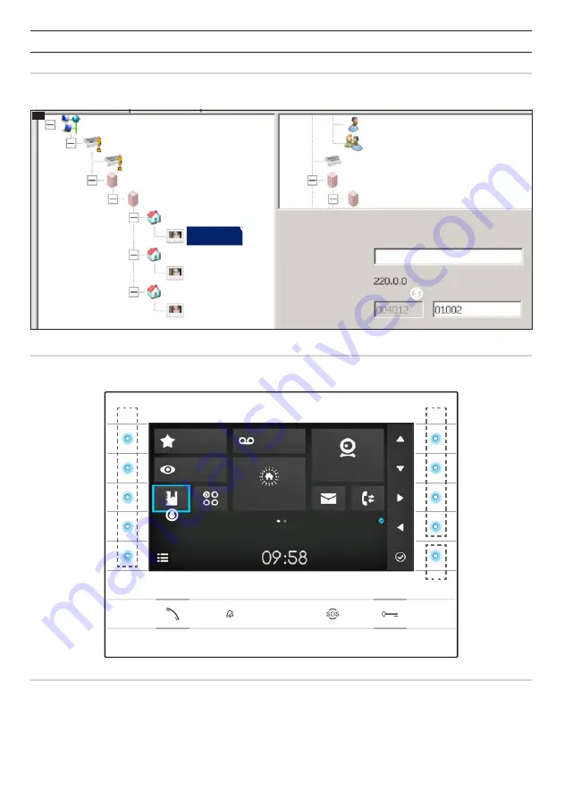
The device is a constituent part of a system based on the Xip system. For this reason the system structure must have been previously
constructed using the PCS Xip software.
K
①
②
③
④
⑤
IP RECV 7
IP RECV 7
IP RECV 7
IP 3 unit
IP 2 unit
IP RECV 7 properties
Name
Address
SIP User Name
IP RECV 7
IP 1 unit
Sub block IP
IP 1 block
ETI
ETI/miniSER
XIP Multi server
Concierge
Group of concierges
ETI
Block IP
Sub block IP
Detecting the "SIP User Name" of the device
K
Create the IP block
①
and Sub block
②
; add the IP units
③
and lastly the IP receivers
④
; select the desired IP receiver. In the properties
window you can see
⑤
the code to use as "
SIP User Name
" to configure the receiver.
Browsing in the interface
Note: The appearance of the home page may vary according to how the system or User interface is configured.
The area highlighted in blue on the display
⑥
indicates the element selected; use the buttons on the right of the receiver
⑦
to move
the selection in the direction indicated by the arrows on the screen; once the desired element is highlighted, press button
⑧
to open
the section connected to it.
The function of buttons
⑨
located on the left of the screen varies depending on what is shown on the screen.
Note: active buttons are highlighted by the blue LED coming on.
Favourites
Video Recording
Entry Panels
Fast Menu
Wednesday
19th March 2014
Home Automation
IP Cameras


