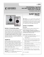
CM-333 Battery Operated with Relay Output Active Infra-red “Hands-Free” Switches Installation Instructions
Section 3: Applications & Set-up
Applications
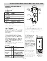
See Diagram 3 for the location of the Dip switches.
DIP Switch Settings
DIP Switch 1
Switch 1 – LED On/LED Off
This switch disables the LED, should this feature be
desired. Factory setting is OFF. This feature will decrease
the battery life if set to ON.
Switch 2 – Audio Enable
Set this switch ON to enable an audible beep every time
the switch is activated. Factory default is OFF. Enabling
this feature will use additional power and decrease the
life of the battery.
Switch 3
– Normal Mode/Fail-Safe Mode
Choose Normal Mode if you wish the N.O. contact to
remain open if the power were to fail. This is the factory
setting.
Choose Fail-safe Mode if you wish the contacts to close
upon power fail. Move the Dip switch to OFF position,
and wire your device to the Common and N.C. wires.
Switch 4
– Toggle
The relay will activate and stay activated until the object is
removed and then presented again.
Dip Switch 2
Battery Strength Meter
To check the battery strength, place an object in front
of the Surewave™ for approximately 5 seconds. The
Surewave™ will beep up to 5 times indicating the battery
charge level. 5 beeps being fully charged. 1-3 beeps
indicates you should change the batteries.
Adjustments
Once the Dip switches have
been set, and the unit is
installed in the frame or
enclosure, apply power to the
unit and observe operation.
Set both potentiometers to
minimum setting initially (fully
counter-clockwise).
Adjust the range potentiometer
by turning the pot in a clockwise
manner, and passing your hand
in front of the unit. Rotate the
pot until the desired range is
obtained. See Diagram 3 for
locations.
Next, adjust the time delay
potentiometer by turning
clockwise until the desired
time delay is obtained. It is
sometimes beneficial to leave
this adjustment set to minimum
and utilize the time delay on the
door operator, if present.
CM-333
Description
1 LED Enable
Green LED flashes while the output is
activated
2 Audio Enable
Piezo buzzer sounds when the output is
activated
3 Fail Safe
Changes the output relay logic.
N/O becomes N/C and N/C becomes N/O
4 Toggle
Relay Toggles on each activation
1
2
1
2
O
N
O
N
43
RELAY
LED
Relay OP
Time
LED Enable
Audio Enable
Sounder
Error/Alarm
LED
Range Adj.
MOM OP
MOM OP
with Alarm
Fail Safe
Diagram 3
Door
Frame
25mm
1"
CM-324/N3
Diagram 4
Wheelchair Sticker
Placement
Function
SW1
SW2 Description
Momentary OFF
OFF
The output operates once and
only re-engages after the object is
removed
Momentary
with alarm ON
OFF
The output operates once, and
only re-engages after the object is
removed. If an object remains in
the detectable area, an alarm will
generate after approximately
30 seconds.
Continuous
Operation
OFF
ON
The output remains activated until
the object is removed.
Page 3 of 4


