
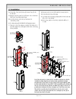
Door Status Sensor
(Closed position)
White = N/O
Orange = COM
Grey = N/C
Push Buttons
Keypads
Strikes
Magnetic Locks
Key Switches
Relays & Timers
Access Control
5502 Timberlea Blvd.,
Mississauga, ON Canada
L4W 2T7
www.camdencontrols.com
Toll Free: 1.877.226.3369
File: CX-ED1259LDesigner
Installation Instructions.indd R3
Revision: 22/02/2018
Part No.: 40-82B205
CX-ED1259-L ‘RIM’ Electric Strike
Page 3 of 3
Orange
White
Grey
Black
Red
Blue
Green
Red
Green
Black
Blue
12V
24V
Black
Red
Blue
Green
(+12V)
(-)
Varistor
(+24V)
(-)
Varistor
5. Connections
6. Wiring
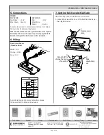
7. Setting Fail-Secure/Fail Safe
A varistor is provided to protect/prevent strike from spikes.
Connect varistor between input wires.
Note: The door strikes are to be powered via a class 2 power
limit output from a control panel or power supply that is UL
listed to UL Burglar Alarm/Access control standards.
How to modify fail-safe to fail-secure or vice versa.
1. Loosen the screw at the back of the Electric strike as per
the diagram below.
A varistor is provided to protect strike from spikes.
Connect varistor to between input wires.
POWER
12V AC/DC
Red/Black: +12V
Blue/Green: Ground
24V AC/DC
Red:
+24V
Black/Blue: -
Green:
Ground
Fail safe
Fail secure
3.
Rotate 180°to
change the mode
of operation
2.
Slide
mechanism
out
1.
Remove cover
plate


