Contents
This document contains proprietary information protected by copyright. All rights
are reserved. No part of this manual may be reproduced by any mechanical,
electronic or other means, in any form, without prior written permission of the
manufacturer. All trademarks and registered trademarks are the property of their
respective owners.
© Copyright Cambridge Audio Ltd 2015.
Cambridge Audio and the Cambridge Audio logo are trademarks of Cambridge
Audio.
Make sure you register your purchase.
Visit: support.cambridgeaudio.com
By registering, you’ll be the first to know
about:
Future product releases
Software upgrades
News, events and exclusive offers plus
competitions!
This guide is designed to make installing and using this product as
easy as possible. Information in this document has been carefully
checked for accuracy at the time of printing; however, Cambridge
Audio’s policy is one of continuous improvement, therefore design
and specifications are subject to change without prior notice.
This document contains proprietary information protected by
copyright. All rights are reserved. No part of this manual may be
reproduced by any mechanical, electronic or other means, in any
form, without prior written permission of the manufacturer. All
trademarks and registered trademarks are the property of their
respective owners.
© Copyright Cambridge Audio Ltd 2015.
Cambridge Audio and the Cambridge Audio logo are trademarks of
Cambridge Audio.
Other brands mentioned are trademarks of their respective owners
and are used for reference purposes only.
Exploded Diagram ...............................................................................................................................3
Front Panel Exploded Diagram ..........................................................................................................4
Product Assy Exploded Diagram ........................................................................................................5
CXN Block Diagram - Master .............................................................................................................6
CXN Block Diagram - Signal Path .......................................................................................................7
CXN Block Diagram - Control Lines ...................................................................................................8
CXN Block Diagram - Clock Signals ....................................................................................................9
CXN Front Panel PCB Schematic ......................................................................................................10
Front Panel Top .................................................................................................................................11
Front Panel Bottom ...........................................................................................................................12
Front panel PCB BOM .......................................................................................................................13
Audio PCB Schematic Power supply ...............................................................................................14
Audio PCB Schematic USB Circuit Powe Supply ............................................................................15
Audio PCB Schematic SPDIF I/O Reply ...........................................................................................16
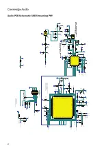
Audio PCB Schematic USB Streaming PHY .....................................................................................17
Audio PCB Schematic DSP and DIR .................................................................................................18
Audio PCB Schematic Masterclocks ................................................................................................19
Audio PCB Schematic DSP Decoupling & SRAM .............................................................................20
Audio PCB Schematic WM8740/1/2 DACs .....................................................................................21
Audio PCB Schematic MCU and Flash .............................................................................................22
Audio PCB Schematic Ethernet and USB HUB ................................................................................23
Audio PCB Schematic ZANDER ........................................................................................................24
Audio PCB Schematic Apple Test Points and EMC Points ..............................................................25
Audio PCB Schematic ANALOGUE STAGE ........................................................................................26
Audio PCB Top ...................................................................................................................................27
Audio PCB Bottom .............................................................................................................................28
Audio PCB BOM .................................................................................................................................29
BUS PCB Schematic ..........................................................................................................................34
Control BUS Top.................................................................................................................................35
Control BUS Bottom ..........................................................................................................................36
Control BUS BOM ..............................................................................................................................37
Front DAUGHTER PCB Schematic ....................................................................................................38
Front Panel DAUGHTER Top PCB .....................................................................................................39
Front Panel DAUGHTER Bottom PCB ...............................................................................................40
Front Panel DAUGHTER PCB BOM ....................................................................................................41
ENCODER PCB Schematic ................................................................................................................42
ENCODER Top & Bottom ..................................................................................................................43
ENCODER PCB BOM......................................................................................................................... 44
SMPS Schematic PCB .......................................................................................................................45
SMPS PCB LAYOUT ............................................................................................................................46
SMPS PCB BOM ................................................................................................................................47
Summary of Contents for CX N
Page 6: ...Service Manual 6 CXN CXN Block Diagram Master ...
Page 7: ...7 CXN Block Diagram Signal Path ...
Page 8: ...Service Manual 8 CXN CXN Block Diagram Control Lines ...
Page 9: ...9 CXN Block Diagram Clock Signals ...
Page 10: ...Service Manual 10 CXN CXN Front Panel PCB Schematic ...
Page 11: ...11 Front Panel Top ...
Page 12: ...Service Manual 12 CXN Front Panel Bottom ...
Page 14: ...Service Manual 14 CXN Audio PCB Schematic Power Supply ...
Page 15: ...15 Audio PCB Schematic USB Circuit Powe Supply ...
Page 16: ...Service Manual 16 CXN Audio PCB Schematic SPDIF I O Reply ...
Page 17: ...17 Audio PCB Schematic USB Streaming PHY ...
Page 18: ...Service Manual 18 CXN Audio PCB Schematic DSP and DIR ...
Page 19: ...19 Audio PCB Schematic Masterclocks ...
Page 20: ...Service Manual 20 CXN Audio PCB Schematic DSP Decoupling SRAM ...
Page 21: ...21 Audio PCB Schematic WM8740 1 2 DACs ...
Page 22: ...Service Manual 22 CXN Audio PCB Schematic MCU and Flash ...
Page 23: ...23 Audio PCB Schematic Ethernet and USB HUB ...
Page 24: ...Service Manual 24 CXN Audio PCB Schematic ZANDER ...
Page 25: ...25 Audio PCB Schematic Apple Test Points and EMC Points ...
Page 26: ...Service Manual 26 CXN Audio PCB Schematic ANALOGUE STAGE ...
Page 27: ...27 Audio PCB Top ...
Page 28: ...Service Manual 28 CXN Audio PCB Bottom ...
Page 34: ...Service Manual 34 CXN BUS PCB Schematic ...
Page 36: ...Service Manual 36 CXN Control BUS Bottom ...
Page 38: ...Service Manual 38 CXN Front DAUGHTER PCB Schematic ...
Page 42: ...Service Manual 42 CXN ENCODER PCB Schematic ...
Page 43: ...43 ENCODER Top Bottom AP33112 2 ...


