background image

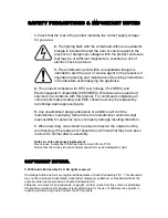
SAFETY PRECAUTIONS & IMPORTANT NOTES 


1.

Check that the rear of the product indicates the correct supply voltage 

for you area. 


2.

 The lighting flash with the arrowhead within an equilateral 

triangle is intended to alert the user or service agent to the 
presence of dangerous voltages within the product enclosure 
that may be of sufficient magnitude to constitute a risk of 
electric shock to persons. 


3.

 The exclamation point within an equilateral triangle is 

intended to alert the user or service agent to the presence of 
important operating and maintenance (Servicing) instructions 
in the literature accompanying the appliance. 
 

4.

 This product complies with EEC Low Voltage (73/23/EEC) and 

Electromagnetic Compatibility (89/336/EEC) Directives when used and 
serviced in accordance with this manual.  For continued compliance all 
components marked safety and EMC critical must only be replaced by 
Cambridge Audio approved parts. 
 

5. 

Any unauthorised design alterations or additions will void the 

manufacturer’s warranty; furthermore the manufacturer cannot accept 
responsibility for personal injury or property damage resulting therefrom. 
 
6. When servicing, care should be taken to observe the original routing 
and dressing of the leads and it should be confirmed that they have been 
returned to normal after re-assembly. 
 

Notes on chip component replacement 

Never reuse a component that has been removed from a PCB 
Notice that the minus side of a tantalum capacitor may be damaged by heat 


COPYRIGHT NOTICE. 


© 2005 Audio Partnership PLC. All rights reserved. 


Cambridge Audio and Azur are registered trademarks of Audio Partnership PLC.


This document 

may not be reproduced, distributed, transmitted, displayed, published, or broadcast without the 
express written prior permission of Audio Partnership PLC. 
Alteration or removal of any trademark, copyright, or other notice from this content is prohibited.


Information provided in this document is provided solely for the use of official service agents in 
repairing and servicing Audio Partnership PLC products.


Summary of Contents for Azur 640C

Page 1: ...____________________ SERVICE MANUAL ________________________________________________________________________ SPECIFICATIONS D A Converter Wolfson WM8740 24 Bit 192kHz Capable Freq response 0 5dB 10Hz to 20kHz THD 92dB Dynamic Range 105dB Channel Separation 75dB Jitter correlated 260pS Digital Outputs Opt and Coax Dimension mm H x W x D 70 x 430 x 310 Weight kg 4 6 AP14839 2 1 ...

Page 2: ...e 11 Front Panel PCB BOM Silver Unit 12 13 Servo PCB Schematic 14 Servo PCB Schematic Power Supply 15 Servo PCB Layout Top Side 16 Servo PCB Layout Bottom Side 17 Servo PCB BOM 18 19 DAC PCB Schematic 20 DAC PCB Layout Top Side 21 DAC PCB Layout Bottom Side 22 DAC PCB BOM 23 Mains Input PCB Schematic 24 Mains Input PCB Layout Top Side 25 Mains Input PCB Layout Bottom Side 26 Mains Input PCB BOM 27...

Page 3: ...ts 5 Any unauthorised design alterations or additions will void the manufacturer s warranty furthermore the manufacturer cannot accept responsibility for personal injury or property damage resulting therefrom 6 When servicing care should be taken to observe the original routing and dressing of the leads and it should be confirmed that they have been returned to normal after re assembly Notes on ch...

Page 4: ...hat safety and EMC critical components are replaced with Cambridge Audio approved parts only CLASS 1 LASER PRODUCT NOTES ON HANDLING THE OPTICAL PICK UP BLOCK OR BASE UNIT The laser diode in the optical pick up block may suffer electrostatic breakdown because of the potential difference generated by the charged electrostatic load etc on clothing and the human body During repair pay attention to el...

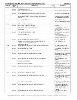
Page 5: ...M C Torx Recessed 1 K Head En Plated silver 7 PY586 6564 010001 000A01 Azur 640C Front panel SILVER 7 PY582 6564 010001 000 01 Azur 640C Front panel BLACK 8 PY587 8564 001001 301 Azur 640C Complete front panel assy Silver REV A 8 PY583 8564 001002 301 Azur 640C Complete front panel BLACK REV A 9 PY563 3200 576690 100 TRANSFORMER 115V 230V AC10V 2A 16 2 0 5A ES 57 669 10 PY541 6050 150010 000A01 PL...

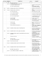
Page 6: ...E ON THE FRONT PANEL AP13322 1 CAMBRIDGE NEW RANGE 105mm DISPLAY WINDOW 1 GLUED IN PLACE ON THE FRONT PANEL AP13436 2 CAMBRIDGE NEW RANGE CD SUB PANEL LEFT POWER 1 FASTENEND IN PLACE INBETWEEN THE LEDGES ON THE FRONT PANEL ALIGN UP THE POWER BUTTON HOLES AP12931 1 CAMBRIDGE NEW RANGE AMP LIGHTGUIDE CUT TO SINGLE PIPE 1 FASTEN TO SUBPLATE LEFT POWER M3 X 6 POZI PAN STP SCREW 1 AFFIXES SINGLE LIGHTG...

Page 7: ...E CD TRANSFORMER PAD 1 POSITION IN PLACE ON BOTTOM PANEL WITH THE FIXING BOLTS THROUGH SUPPLIED HOLES PY563 AP13157 3 CAMBRIDGE AUDIO EI 115 230V 540C 640C TRANSFORMER 1 POSITION ON TRANSFORMER PAD WITH FIXING BOLTS THROUGH SUPPLIED HOLES AP13545 1 CAMBRIDGE AUDIO NEW RANGE CD TRANSFORMER CAN WITH ADHESIVE PAD ADDED 1 SCREENED WITH ARTWORK AP13721 1 POSITION ON TOP OF TRANSFORMER AND PRESS TO STIC...

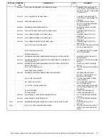
Page 8: ...P12727 1 CAMBRIDGE AUDIO NEW RANGE FRONT PLASTIC SUPPORT 2 RIDGE WITH CAPTIVE M2 6 NUTS 2 POSITION AT FRONT WITHIN SIDE PANELS AP12728 1 CAMBRIDGE AUDIO NEW RANGE REAR PLASTIC SUPPORT 2 RIDGE WITH CAPTIVE M2 6 NUTS 2 POSITON AT REAR WITHIN SIDE PANELS M2 6 X 10 C S POZI PLASTITE 8 TO AFFIX SIDE PANELS TO PLASTIC INSERTS D640C REAR PANEL ASSEMBLY 1 AP13435 2 CAMBRIDGE AUDIO NEW RANGE CD REAR PANEL ...

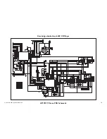
Page 9: ...33K R5 2K7 R6 10K R7 82K R8 1K5 R9 82K C1 100n 5V C2 1000p C3 1000p R10 68K R11 3K3 5V FORWARD SKIP FORWARD SEARCH BACKWARD SKIP BACKWARD SEARCH SW4 SW TACT SW5 SW TACT 5V 3 OPT 1 GND 2 U2 TSOP18 IR RECEI C4 100n R15 330R VSS 14 RB2 11 RC4 6 RC2 8 RC3 7 RB1 12 RB4 OSC2 CLKOUT 3 RB0 13 VDD 1 RB5 OSC1 CLKIN 2 RB3 MCLR VPP 4 RC5 TOCKI 5 RC1 9 RC0 10 U3 16C505 SW6 SW TACT P1 PAD P2 PAD PGND R12 4K7 R1...

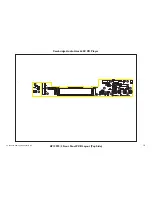
Page 10: ...Cambridge Audio Azur 640C CD Player AP12992 3 Front Panel PCB Layout Top Side To enhance viewing please print to A3 10 ...

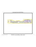
Page 11: ...Cambridge Audio Azur 640C CD Player AP12992 3 Front Panel PCB Layout Bottom Side To enhance viewing please print to A3 11 ...

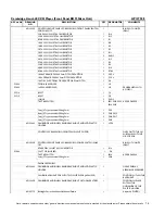
Page 12: ...PER D500SE 2way JST type connector 90deg 2mm 1 CN1 8way JST type connector 90deg 2mm 2 CN2 CN3 7way JST type connector 90deg 2mm 2 CN4 CN7 3way JST type connector 90deg 2mm 1 CN5 AP13344 1 CAMBRIDGE AUDIO NEW RANGE BACKLIGHT AND LCD PLASTIC HOLDER 1 LCD1 CONTROL PCB ASSEMBLY FRONT PANEL SWITCH PCB FIXES ONTO THE L H SUB PANEL WITH M3 M C SCREWS AP12993 3 CONTROL FRONT PANEL PCB ASSEMBLY POWER SWIT...

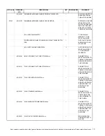
Page 13: ... 280mm 2 CONNECTS THE FRONT PANEL PCB TO THE SERVO PCB RUNS AROUND THE SIDE OF THE CASEWORK AP13621 1 7 WAY LCD CABLE FLAT WIRE STYLE 500mm 1 CONNECTS THE FRONT PANEL PCB TO THE SERVO PCB RUNS AROUND THE SIDE OF THE CASEWORK AP13622 1 7 WAY CRONTROL CABLE 520mm 1 CONNECTS THE FRONT PANEL PCB TO THE SERVO PCB RUNS UNDER THE CD MECH THEN AROUND THE OUTSIDE OF THE CASEWORK AP13623 1 3 WAY STANDBY CAB...

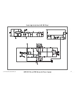
Page 14: ...18 S VCC 19 VIN4 20 OUT 4 21 PVCC4 22 OUT 4 23 PW GND 24 U6 TA2092N R15 10K R39 10K R14 10K R13 10K R12 10K 5V R11 10K R6 220K R7 68K R5 15K R9 47K C8 0 015uF C76 47pF C74 47uF 16V R8 10K C75 0 01uF C6 0 0027uF 1 2 3 CN1 DIGITAL OUT 5V R10 47R C11 0 047uF C10 47uF 16V C9 47uF 16V 1 2 3 4 5 6 7 8 9 10 11 12 13 14 15 16 CN16 MECH 1 2 3 4 5 6 CN15 MOTOR DRIVE 8V C56 220uF 16V C59 100nF R64 10K 5V C58...

Page 15: ... 12K C42 390pF C38 390pF 3 2 1 8 4 U4 A NJM2100 FOR 340C PLEASE USE TS922IN 5 6 7 U4 B NJM2100 FOR 340C PLEASE USE TS922IN R73 47K C33 10pF C34 100uF 16V 1 2 3 CN9 GND R71 47K C43 100uF 16V R70 47K C35 0 1uF 5V L CH R CH 8V R81 47K C36 10pF R79 15K R72 15K C37 220uF 16V 1 2 3 CN10 GND L CH R CH GND 1 2 3 4 5 CN13 DIG DATA 1 2 CN14 MCLK R68 47R R69 47R 3 4 5 RL1 B 1 2 RL1 A 6 7 8 RL1 C R83 120R 0 5...

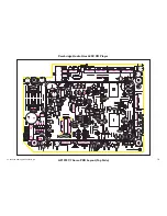
Page 16: ...Cambridge Audio Azur 640C CD Player AP12927 7 Servo PCB Layout Top Side To enhance viewing please print to A3 16 ...

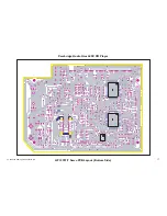
Page 17: ...Cambridge Audio Azur 640C CD Player AP12927 7 Servo PCB Layout Bottom Side To enhance viewing please print to A3 17 ...

Page 18: ... 82K 0 125W METAL FILM RESISTOR 1 R59 100K 0 125W METAL FILM RESISTOR 1 R63 220K 0 125W METAL FILM RESISTOR 1 R6 5p CERAMIC COG 50 100V 5mm PITCH CAPACITOR 1 C1 15p CERAMIC COG 50 100V 5mm PITCH CAPACITOR 2 C16 C17 25p CERAMIC COG 50 100V 5mm PITCH CAPACITOR 2 C80 C81 47p CERAMIC COG 50 100V 5mm PITCH CAPACITOR 1 C76 56p CERAMIC COG 50 100V 5mm PITCH CAPACITOR 1 C73 470p CERAMIC 50 100V 5mm PITCH ...

Page 19: ...PY559 8550 TRANSISTOR PNP C8550 2 Q9 Q10 PY558 9014C TRANSISTOR NPN 9014C 1 Q13 DIODE 1N4148 2 D8 D9 D10 D11 DIODE IN4004 3 D2 D3 D4 D5 2 Way 2mm Pitch JST Type connector XIN X1 UNREG OUT X1 MUTE X1 3 CN17 CN20 CN21 3 Way 2mm Pitch JST Type connector DIGITAL OUT X1 1 CN1 5 Way 2mm Pitch JST Type connector DATA OUT X1 Draw drive X1 2 CN2 CN8 6 Way 2mm Pitch JST Type connector MOTOR DRIVE 1 CN15 7 W...

Page 20: ...PUT 3 U11 APTX179AT R28 430R 2W C25 100n LRCIN 1 DIN 2 BCKIN 3 MODE8X 4 SCLK 5 DIFFHW 6 DGND 7 DVDD 8 AVDDR 9 AGNDR 10 VMIDR 11 VOUTRP 12 VOUTRN 13 AGND 14 AVDD 15 VOUTLN 16 VOUTLP 17 VMIDL 18 AGNDL 19 AVDDL 20 ZERO 21 RSTB 22 CSBIWO 23 MODE 24 MUTEB 25 MD DM0 26 MC DM1 27 ML I2S 28 U7 WM8740 3 2 1 8 4 U6 A NE5532 5 6 7 U6 B NE5532 C5 10n PE C4 10n PE C40 1n5 ML C38 1n5 ML VA2 VA1 R22 4k7 R23 4k7 ...

Page 21: ...Cambridge Audio Azur 640C CD Player AP13111 4 DAC PCB Layout Top Side To enhance viewing please print to A3 21 ...

Page 22: ...Cambridge Audio Azur 640C CD Player AP13111 4 DAC PCB Layout Bottom Side To enhance viewing please print to A3 22 ...

Page 23: ...lectrolytic Capacitor 4 C2 30 32 46 10uF NP 25V Radial Non polar Electrolytic 5 C6 21 23 45 47 100uF NP 16V Radial Non polar Electrolytic 2 C34 35 2200uF 35V Radial Electrolytic Capacitor 2 C3 24 1N4004 Standard rectifier diode 5 D1 2 3 4 5 1N4148 Standard signal diode 2 D6 7 PY014 C8050 Small signal transistor NPN TO92 2 Q2 4 PY020 C9012 Small signal transistor PNP TO92 2 Q1 3 7805 5V 1A regulato...

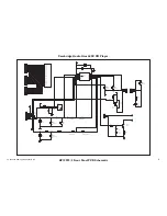
Page 24: ...AP13637 3 Mains Input Schematic earth FU1 20MM F1AL FU2 20MM F1AL FU3 20MM T1AL J1 BLUE J3 BROWN L N E CN3 IEC SOC C2 X1 10n C1 X1 10n 1 2 3 CN1 CONN H3 1 2 3 CN2 CONN H3 J2 BLACK LK2 230V LK1 115V To enhance viewing please print to A3 24 ...

Page 25: ...Cambridge Audio Azur 640C CD Player AP13637 2 Mains Input PCB Layout Top Side To enhance viewing please print to A3 25 ...

Page 26: ...Cambridge Audio Azur 640C CD Player AP13637 2 Mains Input PCB Layout Bottom Side To enhance viewing please print to A3 26 ...

Page 27: ... OR LK2 AP13903 1 160mm GREEN YELLOW GROUNDING WIRE WITH 1 RING M4 AWG 18 1 IEC CONNECTOR EARTH TAG TO GROUND ON CHASSIS 3 way 2 5mm pitch JST type connector 2 CN1 CN2 IEC MAINS SOCKET PC1287 1 CN3 FIRST TECH AS PER D500 SE CD PLAYER 2 BOLT M3x10 BLACK 1 IEC CONNECTOR TO PCB 2 LOCK WASHER M3 1 IEC CONNECTOR TO PCB 2 NUT M3 HEX M3X5 5X2 4mm 1 IEC CONNECTOR TO PCB Cambridge Azur 640C CD Player Mains...

Page 28: ...Cambridge Audio Azur 640C CD Player IC Pin Layout Details Front Panel PCB PIC16C505 U3 28 ...

Page 29: ...DAC PCB WM8740 U7 NE5532 U5 U6 29 ...

Page 30: ...74HC14 U2 U10 APTX179A U11 SERVO PCB 30 ...

Page 31: ...TA2153FN U1 TC9462F U2 31 ...

Page 32: ...TLCS 870 MCU U3 32 ...

Page 33: ...TA2092 U6 33 ...

Page 34: ... CARTON LABEL MODEL NO UK BLACK 1 FOR BOX PY515 M2 6 x 8 MC Torx Recessed Screw BLACK 8 TOP PANEL SCREWS PY146 AP11782 1 OPUS CONTROL BOX BUTTON BLACK 1 POSITION IN PLACE ON THE FRONTPANEL PY531 CAMBRIDGE NEW RANGE FOOT MOULDING BLACK 4 POSITION IN PLACE ON BOTTOM PANEL CAMBRIDGE NEW RANGE AMP 7mm TAC SWITCH BUTTON BLACK 5 POSITION IN PLACE ON THE FRONT PANEL Cambridge Azur 640C CD Player Silver B...

Reviews: