


24
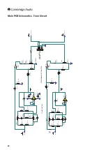
Volume Control PCB Schematics
© COPYRIGHT
The Audio Partnership
Gallery Court
Hankey Place
LONDON SE1 4BB
Tel : +44 (0)171 940 2200
Fax : +44 (0)171 940 2233
DRAWN BY
CHECKED BY
DATE
DRAWING TITLE
DRAWING No.
PAGE
SHEET TITLE
GENERAL NOTES
Dave M
08/02/12
350A & 351A Volume PCB
Volume Control PCB
AP24041/3
1/1
1.
2.
3.
4.
5.
7
3
2
Ch
9
VR1:A
50k log
ALPS volume pot with motor
6
4
5
VR1:B
50k log
ALPS volume pot with motor
Out.
Out.
Out.
Pot Shield
Out.
C1
Ceramic
10nF 50V
Input Gnd
1
2
CA1
Solder on to volume pot motor
120mm tinned cable
Cable assembly
VOLUME CONTROL MOTOR
VIEWED FROM REAR
BLUE DOT
RED
BLACK
1
2
3
4
5
6
CA2
Rev 3 change: CN1 connector changed to CA2 solder-in cable assembly
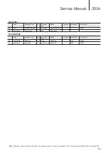
Note:
Resistors, capacitors and other generic components are not usually stocked by the manufacturer. Please obtain these locally.
Volume Control PCB BOM
RESISTORS VARIABLE
Value
Description/Type
Qty
Component
Ident
ManPN
Tolerance
PackageInfo
Service Part Numbers
1
50k log
ALPS volume pot
with motor
1
VR1
RK16812MG082
16mm
Motorised Volume Pot
PY1603
CAPACITORS
Value
Description/Type
Qty
Component
Ident
ManPN
Tolerance
PackageInfo
AP Numbers
2
10nF 50V
Ceramic
1
C1
1N5402
10%
2.5mm Pitch
MISCELLANEOUS
Value
Description/Type
Qty
Component
Ident
ManPN
Tolerance
PackageInfo
AP Numbers
3
120mm tinned
cable
Cable assembly
1
CA1
AP26761/1
2.5mm Pitch
Solder on to volume pot motor
4
60mm cable
assembly
Cable assembly
1
CA2
AP26762/2
2.5mm Pitch
Solder to CN1 on volume PCB
PCB
Value
Description/Type
Qty
Component
Ident
ManPN
Tolerance
PackageInfo
AP Numbers
5
AP Numbers
Schematic is
AP25801/3
Gerber is
AP25802/1
Construction details
AP25803/1
Test Procedure N/A
Summary of Contents for AZUR 351A
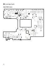
Page 16: ...16 Main PCB Gerbers ...
Page 17: ...351A Service Manual 17 Main PCB Gerbers ...
Page 18: ...18 Main PCB Gerbers ...