Cambridge Audio Azur 340A Service Manual Download Page 4

AP14861/4

AP PART 

No.

DRAWING NO

DESCRIPTION

QTY

COMMENTS

Chassis Assembly

AP14160/1

Bottom Panel

1

PY541

AP12652/2

Foot Moulding Silver

4

Position In Place on Bottom Panel

PY544

AP12883/3

 Foot Pad

4

Affix on Foot Using Adhesive Surface

M3 X 8 Plastite Pozi Pan

4

Fix Feet To Bottom Panel.

7mm Plastic Support

9

Push Snap Fit On Bottom Panel

7mm Plastic Support

4

Resting Under PCB fastened to Bottom Panel

AP14775/1

7mm Plastic Standoff ( Square Snap - In)

6

Fastening PCB to Bottom Panel

M3 X 8 Plastite Pozi Pan

6

To hold PCB to Square snap-in Stand-offs

AP14561/3

Transformer toroidal 230V

1

Transformer bolt M8  56mm thread length

1

Supplied with Transformer.  Secures transformer

Dished transformer plate 70 mm diam

1

Supplied with Transformer.  On top of transformer

Rubber Washer

2

Supplied with Transformer.  One is fitted under the 
transformer and one on the top, under dished washer

M8 nut

1

Supplied with Transformer.  Secures transformer

M8 plain washer

1

Supplied with Transformer.  Secures transformer

M8 locking washer

1

Supplied with Transformer.  Secures transformer

AP15528/1

Cambridge Toroidal 67mm label 

1

Stick to top of dished transformer plate 70 mm diam.

AP14862/2

Insulation Sheet

1

To Be  Positioned Over Standoffs Under Power PCB

M4 X 12 Pozi Pan Machine Bolt

1

Fix Through Earthing Point hole on Bottom Panel

M4 Nut Standard

1

Used To Fix Above Bolts

M4 Lock Washer

1

For Earth Bolts

Earth point label

1

Place next to earth point bolt on bottom of chassis

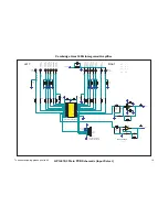
PCB Gerber  AP14Main PCB Assembly BOM

1

Fixes onto the Bottom Panel With 7mm Plastic Standoffs. 
Built to BOM AP15173/2

Front Panel Assembly

AP14159/1

Sub Panel 

1

Fasten in place between the Ledges of the Front Panel, Align 
Up The Power Button Holes

AP12931/1

Lightguide

3

Fasten To Subplate.   Input select LEDs

AP12931/1

Lightguide (half of)

0.5 Fasten To Subplate.   Power LED

M3 X 6 Pozi Pan Stp Screw

4

Affixes Three Lightguide To Subplate

PY638

AP14157/1

Front Panel (Punched And Printed) Silver

1

Extrusion Details AP12738* & Screened With Artwork 
AP14826/1 & AP14828/2

AP12935/1

IR Lens

1

Glued In Place On The Front Panel

M3 X 6 C/S Pozi  Machine Screw

7

Fasten The Sub Plate to the Front Panel. Only 7 screws are 
fitted out of a possible 8.  See drawing AP15536/1

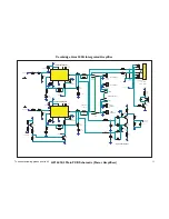
PCB Gerber  AP14IR PCB Assembly (part of F/P PCB assembly)

1

Fitted onto the Front Panel, bom is AP15185/2

Washer Nylon M3, 1mm Thk

1

Fitted between Front Panel and IR PCB

M2.6 x 4mm Pan hd Poz Taptite

1

Use to fix IR PCB onto SubPanel

AP12934/1

7mm TAC Switch Cushion

6

Position on the 7mm tact switch Buttons, down the main 
shaft affix using adhesive provided on the cushion.

AP12925/1

7mm TAC Switch Button

6

Position In Place On The Front Panel

AP12926/2

7mm  Push Switch Button

2

Fitted to SW1 & 2 on main PCB

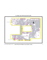
PCB Gerber  AP14Front Panel & MicroController PCB Assembly 

BOM

1

Fixes onto the Sub Panel With M3 M/C Screws. Built to BOM 
AP 15185/2

M3 X 6 Pozi Pan Machine Screw

7

Used For Fixing The Front Panel Pcb's To The Subplate 
Standoff's

Side Panel Assembly

AP12725/2

Pressed Side Panel (2 Ridge)

2

AP12727/1

Front Plastic Support (2 Ridge With Captive 
M2.6 Nuts)

2

Position at Front within Side Panels

AP12728/1

Rear Plastic Support (2 Ridge With Captive M2.6 
Nuts)

2

Position at Rear within Side Panels

M2.6 X 8 C/S Pozi Plastite

8

To Affix Side Panels To Plastic Inserts

Rear Panel Assembly

AP14162/2

Rear Panel Printed 

1

Screened With Artwork AP14830/3

M3 X 10 Pozi Pan Plastite

8

To fix speaker terminal and Phono sockets connectors to 
Rear Panel

M4 X 8 Pozi Pan Plastite

2

To fix IEC Power connector to Rear Panel

Cambridge Azur 340A Main Assembly BOM

4

Summary of Contents for Azur 340A

Page 1: ...ERVICE MANUAL ________________________________________________________________________ SPECIFICATIONS Power Output 40W into 8Ω 50W into 4Ω Max Power Consumption 345W Total Harmonic Distortion 1kHz 0 009 20kHz 0 09 Frequency Response 1dB 5Hz 50kHz S to N Ration unweighted 99dB Slew Rate into 8Ω 20V uS Dimensions HxWxD mm 70 x 430 x 310 Inches 2 8 x 16 9 x 12 2 Weight Kg 6 2 Lbs 13 6 AP15844 1 1 ...

Page 2: ...ayout Top Side 7 Micro controller PCB Layout Bottom Side 8 Front Panel PCB Assembly BOM 9 Main PCB Schematic Input Select 10 Main PCB Schematic Power Amplifiers 11 Main PCB Schematic Power Supplies 12 Main PCB Schematic Tone Control 13 Main PCB Layout Top Side 14 Main PCB Layout Bottom Side 15 Main PCB BOM 16 18 IC Pin Layout Details 19 20 Silver Black Differences BOM 21 2 ...

Page 3: ...s 5 Any unauthorised design alterations or additions will void the manufacturer s warranty furthermore the manufacturer cannot accept responsibility for personal injury or property damage resulting therefrom 6 When servicing care should be taken to observe the original routing and dressing of the leads and it should be confirmed that they have been returned to normal after re assembly Notes on chi...

Page 4: ...gn Up The Power Button Holes AP12931 1 Lightguide 3 Fasten To Subplate Input select LEDs AP12931 1 Lightguide half of 0 5 Fasten To Subplate Power LED M3 X 6 Pozi Pan Stp Screw 4 Affixes Three Lightguide To Subplate PY638 AP14157 1 Front Panel Punched And Printed Silver 1 Extrusion Details AP12738 Screened With Artwork AP14826 1 AP14828 2 AP12935 1 IR Lens 1 Glued In Place On The Front Panel M3 X ...

Page 5: ...oket CN3 on main PCB to Chassis earth stud M4 Nut Standard 1 Used To Fix earth lead to earth stud M4 Lock Washer 1 For above nut LED wireform is attached to main PCB Glue power LED into light guide Lidding AP13340 1 Lidding Tape For Front And Rear Panels 2 Fix To The Correct Surfaces For Lid AP13342 1 Lidding Tape For Side Panels 2 Fix To The Correct Surfaces For Lid PY640 AP14161 1 340A Top Panel...

Page 6: ...NNEL LED D5 CHANNEL LED D6 CHANNEL LED SW2 CD SW3 TUNER DAB SW5 AV MD SW1 AUX PHONO SW6 TAPE MON SW4 DVD 5V 3 OPT 1 GND 2 U3 TSOP18 IR RECEI C1 100n strobe data clock clock data strobe vol up vol down vol up vol down C3 47u 16V R3 220R C4 100n 1 2 3 4 5 6 7 8 CN2 H8 2 54mm 90 DGND 5V IR RECEIVER AUX PHONO CD TUNER DAB TAPE MON DVD AV MD 1 2 3 CN3 CONN H3 1 2 3 CN4 CONN H3 MOTOR CONTROL CONN TO MAI...

Page 7: ...Cambridge Azur 340A Intergrated Amplifier AP14518 1 Microcontroller PCB Board Layout Top Side To enhance viewing please print to A3 7 ...

Page 8: ...Cambridge Azur 340A Intergrated Amplifier AP14518 1 Micrcontroller PCB Board Layout Bottom Side To enhance viewing please print to A3 8 ...

Page 9: ...LE VISHAY 1 U3 As used in 540A 3001 183600 001 PY064 FLAT TOP BLUE LEDS AS PER CURRENT CAMBRIDGE 6 D1 D6 Please use flat top LED at standard Azur height ICP Picoplex PF 50 6 way male header 1 CN1 Vertical H8 2 54mm 90 1 CN2 Right angle connector 8 way H2 2 54mm 90 1 CN5 Right angle connector 2 way H3 2 54mm 90 1 CN3 Right angle connector 3 way AP14897 1 Azur 340A IR PCB cable 1 2400 020200 000 Tac...

Page 10: ...C13 22p R32 220K R33 10k R34 10k R35 10k R36 10k R37 100K R38 100K R39 100K R40 100K R41 100R R46 100R R47 100R C26 100nF 100V L CH IN R CH IN R50 220K R51 220K 2 1 CN9 A DUAL PHONO 3 CN9 B DUAL PHONO LEFT RIGHT TAPE RETURN RIGHT TAPE RETURN LEFT 1 2 3 4 5 6 7 8 J2 H8 2 54mm 90 5V INPUT TAPE SELECT SWITCH MUTE MICROCONTROLLER BOARD CONNECTOR OUTPUT RELAY DC OFFSET DATA CLOCK STROBE 2 3 5 6 A B C D...

Page 11: ...72 47K R73 47K R74 47K Q2 BC337 AMP MUTE AMP MUTE 28V HI MUTE SW2 A SW DPDT SW2 B SW DPDT SPEAKER B ON OFF RSW1 RSW2 R L GND LSW1 LSW2 2 4 3 1 7 8 5 CN1 HEADPHONE JACK R61 220R 3W C R62 470R 1W C R63 220R 3W C R64 470R 1W C 1 2 CN2 A SPKR 4 WAY 4 3 CN2 B SPKR 4 WAY 5 6 CN2 C SPKR 4 WAY 8 7 CN2 D SPKR 4 WAY LEFT SPEAKER A LEFT SPEAKER B RIGHT RIGHT 3 4 5 RL1 B 12V 8A RELAY 6 7 8 RL1 C 12V 8A RELAY ...

Page 12: ...A04 10 D5 1N4002 D6 1N4002 D7 1N4002 D8 1N4002 J7 TERMINAL green J9 TERMINAL purple J10 TERMINAL blue C45 1000u 35V C46 470u 35V VI 1 VO 3 GND 2 U5 7805 C47 47u 16V C48 47n poly VI 1 VO 3 GND 2 U8 7815 VI 2 VO 3 GND 1 U9 7915 C49 100u 25V C50 100u 25V 5V C51 47n poly C52 47n poly C53 47n poly 15V 15V FROM TRANSFORMER 20V J3 TERMINAL J4 TERMINAL J8 TERMINAL MAINS SWITCH PCB OPAMP SUPPLY MICROCONTRO...

Page 13: ... 1 8 4 U2 A NE5532 5 6 7 U2 B NE5532 R CH IN L CH IN POWER AMP RIGHT POWER AMP LEFT R52 150k R54 150k R59 150k R60 150k 1 3 2 VR1 A 20K MOTORISED DUAL POT 4 6 5 VR1 B 20K MOTORISED DUAL POT 4 6 5 VR4 B MN20K BALANCE 1 3 2 VR4 A MN20K BALANCE 1 3 2 VR2 A B20K LINEAR 4 6 5 VR2 B B20K LINEAR 1 3 2 VR3 A B20K LINEAR 4 6 5 VR3 B B20K LINEAR ZERO LOSS WHEN CENTRAL TONE CONTROL VOLUME BALANCE CONTROL TRE...

Page 14: ...Cambridge Azur 340A Intergrated Amplifier AP14476 4 Main PCB Board Layout Top Side To enhance viewing please print to A3 14 ...

Page 15: ...Cambridge Azur 340A Intergrated Amplifier AP14476 4 Main PCB Board Layout Bottom Side To enhance viewing please print to A3 15 ...

Page 16: ...h 3 0mm 2 C9 C15 330pF Polyester Pitch 5 0mm 2 C1 C10 10nF X1 Mains rated Ceramic Pitch 5 0mm 2 C34 C35 EMC Suppression 47nF Polyester Pitch 5 0mm 10 C4 C5 C7 C8 C16 C17 C48 C51 C53 100nF Ceramic 100V Pitch 5 0mm 3 C2 C26 C36 150nF Polyester Pitch 5 0mm 2 C6 C11 470nF X2 Mains rated Polypropylene Pitch 22 5mm 1 C28 EMC C44 is alternative fit for 27 5 mm pitch 10uF Electrolytic 16V Pitch 2 0mm 4 C3...

Page 17: ...se to PCB M3 x 10 Taptite Power Amp IC Fix Screw 2 Fix IC tab to heatsink M3 Power Amp IC Insulating Bush 2 Insulate fix screw from IC tab Precut washer type K177 NA 617 Power Amp IC Insulating Washer 2 K177 is the material type NA means no adhesive Self adhesive version would be technically acceptable Dwg no AP14899 1 Power Amp Heatsinks 2 Black anodised 6510 150310 000 Pressure board Power Amp I...

Page 18: ...0V TV 8 1 SW3 mains switch Gerber AP14477 4 1 Schematic AP14476 4 Gerber file is AP14477 4 PCB Construction details AP14478 4 Please mark board POP REV A NOTES Note 4 All capacitors 85 degC rating or above Note 1 C23 C39 Components not fitted Note 2 All resistors larger than 0 25W to be stood off the board by 5mm Note 3 All resistors 1 tolerance 18 ...

Page 19: ...Cambridge Audio Azur 340A Amplifier IC Pin Layout Details Front Panel PCB PIC16F72 I SP U1 BA6218 U2 TSOP1836 37 U3 19 ...

Page 20: ...Main PCB NE5532 U1 U2 TC9163AF U4 LM3886T U6 U7 20 ...

Page 21: ...SCREENED WITH ARTWORK AP13679 2 CAMBRIDGE NEW RANGE AMP 7mm TAC SWITCH BUTTON 6 POSITION IN PLACE ON THE FRONT PANEL CAMBRIDGE NEW RANGE AMP 7mm PUSH SWITCH BUTTON 2 POSITION IN PLACE ON THE FRONT PANEL PY531 CAMBRIDGE NEW RANGE FOOT MOULDING 4 POSITION IN PLACE ON BOTTOM PANEL PY641 340A Top Panel Black 1 POSITION ON TOP OF THE PRODUCT PY515 M2 6 x 8 MC Torx Recessed Black 8 TOP PANEL SCREWS Camb...

Reviews: