TLC Scanner 4
Instruction Manual, June 2018
Page 8
3.4
Connections
3.4.1 Power supply
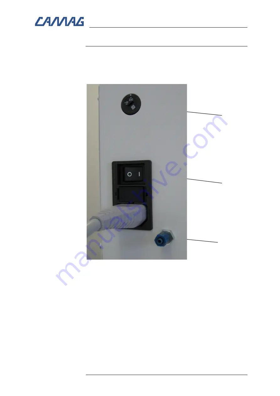
The left side of the Scanner 4 shows the power socket with the
ON/OFF switch (2), the voltage selector-switch (1) and the connec-
tion (tubing nipple) for the nitrogen gas supply (3).
Fig. 3: The power connection
Before connecting the Scanner 4 to the wall outlet check whether
the voltage selector-switch (1) is set in the appropriate position
matching the mains power voltage of your laboratory
The housing of the power socket also contains the two fuses.
All Scanners are fitted with the fuse matching the voltage range of
the voltage selector switch. Two extra fuses are supplied.
Connect the Scanner 4 to the power supply.
(1)
(1)
(3)
(2)
Summary of Contents for 027.6200
Page 1: ...INSTRUCTION MANUAL TLC SCANNER 4 ...
Page 22: ......


