Calumet GSA Manual Download Page 9

GSA


Gas-Fired Steam Boilers – 

Boiler Manual

9

Part Number 550-110-738/0703

General

3

Install piping

1.

Pipe before installing controls. Connect return piping after jacket
is attached. Connect supply piping before or after jacket is
attached.

Failure to properly pipe the boiler may result in
improper operation and damage to the boiler or
building.

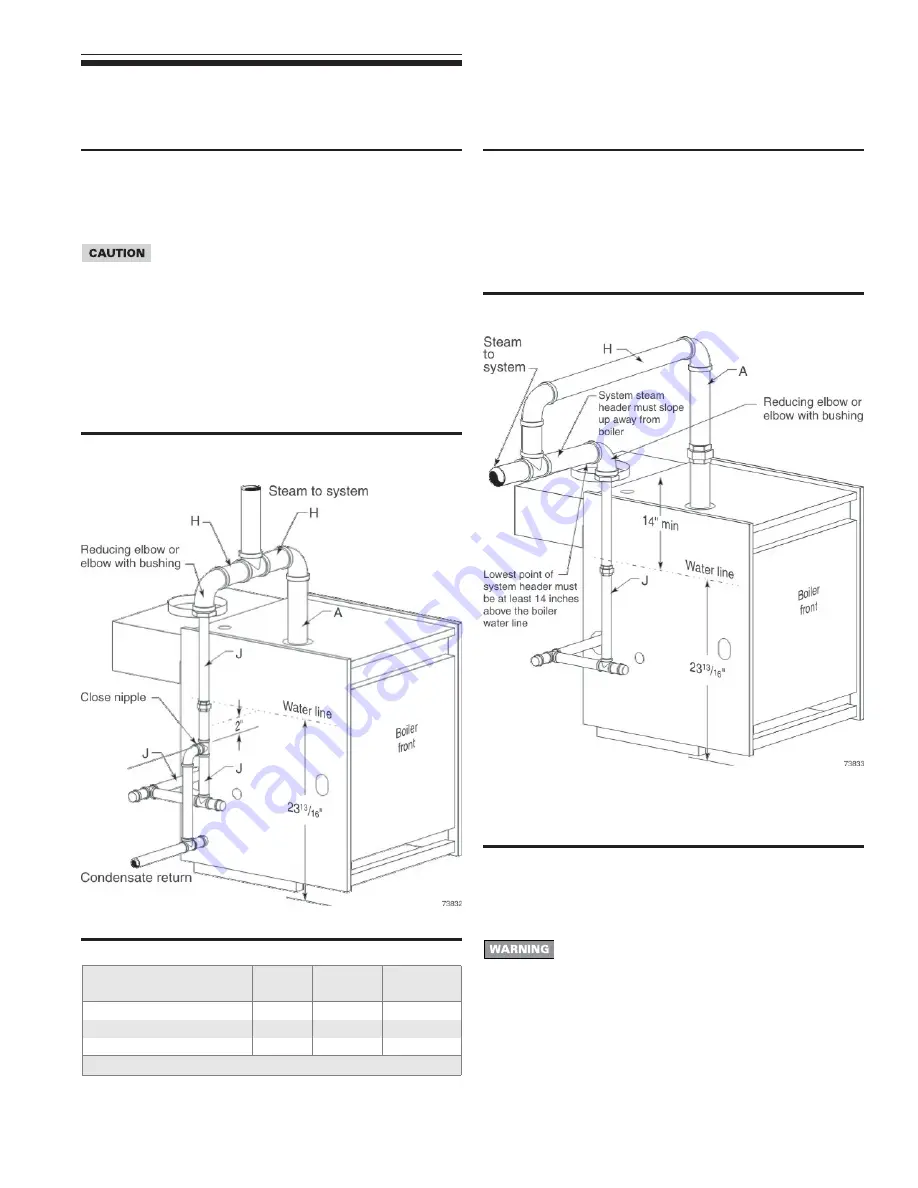
2. See Figure 5 and Table 5. Pipe exactly as shown. Satisfactory

operation of a steam heating system depends on adequate
condensate return to boiler to maintain a steady water level.
Avoid adding raw makeup water. Where condensate return is
not adequate, install low water cutoff/pump control, condensate
receiver and condensate boiler feed pump. Refer to Table 7,
page 10, for sizing. See page 7, Table 4, for tapping locations.

Table 5

Recommended pipe sizing

Boiler model number

Riser (A) Header (H)

see Note

Equalizer (J)

GSA-075 and GSA-100

2"

2"

1½"

GSA-125 through GSA-175

2½"

2 ½"

1½"

GSA-200 and GSA-250

3"

3"

1½"

Note

: 24" minimum from waterline to header.

Figure 5

Recommended piping, piping for parallel-
flow systems only.

Connecting to counterflow piping

Apply the recommended piping in Figures 4 through 7 only when
connecting to a parallel-flow system. When connecting to a
counterflow system, the boiler steam supply must connect into the
top of the counterflow system header, as shown in Figure 6.

Figure 6

Connection to counterflow steam piping

Relief valve

Install relief valve in tapping on top of boiler. See Table 4, page 7,
for control tapping locations. See the tag attached to the relief valve
for manufacturer’s instructions.

Follow the steps below to avoid potential severe
personal injury, death or substantial property damage.

• When installing the relief valve, ensure that all

connections, including the valve inlet, are clean and
free from any foreign matter.

• Mount the relief valve only in the vertical position,

directly connected to the tapping designated in the
manual on top of the boiler.

• Use pipe compound sparingly, or tape, on external

threads only.

• Do not use a pipe wrench! Use proper type and size

wrench on wrench pads only.

Summary of Contents for GSA

Page 1: ...ersonal injury or property damage Special instructions on installation operation or maintenance that are important but not related to personal injury or property damage INSTALLER Read all instructions...

Page 2: ...ubstantial property damage When servicing boiler 1 To avoid electric shock disconnect electrical supply before performing maintenance 2 To avoid severe burns allow boiler to cool before performing mai...

Page 3: ...e room must provide the following minimum clearances in all directions to the boiler and components Jacket and flue collector sides rear 6 inches Jacket front 18 inches Vent pipe other than Type B ven...

Page 4: ...ons will occur causing severe personal injury or death Inspect existing chimney before installing boiler Failure to clean or replace perforated pipe or tile lining will cause severe personal injury or...

Page 5: ...detergents and cleaning solvents found in household laundry rooms Adhesives used to fasten building products and other similar products Areas likely to have contaminants Dry cleaning laundry areas and...

Page 6: ...cation continued Exhaust fans and air movers The appliance space must never be under a negative pressure Always provide air openings sized not only to the dimensions required for the firing rate of al...

Page 7: ...upward at least per lineal foot toward chimney or vent and support with hangers to prevent sagging 4 Breeching must not be connected to any portion of a mechanical draft system that can operate under...

Page 8: ...th 3 8 diameter hole in vent damper hole Minimum clearances Provide a minimum of 6 between the vent damper and any combustible material See Minimum clearance to combustible materials page 3 for minimu...

Page 9: ...3 3 1 Note 24 minimum from waterline to header Figure 5 Recommended piping piping for parallel flow systems only Connecting to counterflow piping Apply the recommended piping in Figures 4 through 7 on...

Page 10: ...arge amounts of steam and or hot water Therefore to reduce the potential for bodily injury and property damage a discharge line MUST be installed that Is connected from the outlet to a safe point of d...

Page 11: ...ar floor close to floor drain to eliminate potential of severe burns Do not plug valve or place any obstruction in blowdown line 3 Water feeders are not recommended for primary control A low water cut...

Page 12: ...n cap and tee b Install ground joint union for servicing when required c Install manual shutoff valve in gas supply piping outside boiler jacket when required by local codes or utility requirements d...

Page 13: ...Code Part 1 and any local codes Figure 11 Field wiring connections service switch and thermostat or end switch provided by installer 6 Field wiring Wiring connections Boiler is shipped with controls...

Page 14: ...ease Failure to properly clean can result in violent fluctuations of water level water passing into steam mains or high maintenance costs on strainers traps and vents Do not use petroleum based cleani...

Page 15: ...ning or sealing compounds in boiler system Severe damage to boiler will occur resulting in substantial property damage 1 Check system piping for leaks If found shut down boiler and repair immediately...

Page 16: ...installed controls If boiler has an additional high limit low water cutoff or other controls test for operation as outlined by manufacturer Burners should be operating and should go off when controls...

Page 17: ...ighted following the Lighting Instructions in this manual and on boiler Vent damper will remain closed until a call for heat 2 Call for heat When thermostat circuit closes the boiler vent damper is en...

Page 18: ...the appliance 5 When equipped with Johnson Controls vent damper Model M35 manually rotate damper blade in direction of arrow to Open position indicated on damper assembly 6 Turn gas control knob clock...

Page 19: ...nspect the appliance and to replace any part of the control system and any gas control which has been under water 1 Stop Read the safety information above on this label 2 Set the thermostat to lowest...

Page 20: ...Service and maintenance Service technician see following pages for instructions Owner maintenance see User s Information Manual for instructions A NNNUAL START UP Inspect Reported problems Boiler area...

Page 21: ...Piping 1 Check the boiler interior piping and all system piping for signs of leaks 2 Repair any leaks before proceeding Do not use petroleum based cleaning or sealing compounds in boiler system Severe...

Page 22: ...per on page 15 2 Check gas piping per pages 12 and 14 verifying no indications of leakage and all piping and connections are in good condition 3 Read the Lighting Instructions page 18 or 19 whichever...

Page 23: ...the heating season to verify the valve and discharge piping flow freely If corrosion and or deposits are noticed within the valve body testing must be performed more often A try lever test must also...

Page 24: ...ns pages 18 and 19 If gas is available and you cannot obtain a pilot flame try purging the gas line and cleaning pilot and pilot gas tubing Follow Lighting Instructions again If you still cannot obtai...

Page 25: ...to closed position Close thermostat contacts Vent damper will rotate to open position Is 24VAC present across gas valve terminals Remove damper harness from damper harness plug TEMPORARILY install jum...

Page 26: ...n assembly flue collector draft diverter vent damper and base assembly 13 Replacement parts The boiler contains ceramic fiber and fiberglass materials Use care when handling these materials per instru...

Page 27: ...738 0703 Figure 17 Jacket assembly 13 Replacement parts continued The boiler contains ceramic fiber and fiberglass materials Use care when handling these materials per instructions on page 32 of this...

Page 28: ...GSA Gas Fired Steam Boilers Boiler Manual 28 Part Number 550 110 738 0703 Figure 18 Controls and trim 13 Replacement parts continued...

Page 29: ...GSA Gas Fired Steam Boilers Boiler Manual 29 Part Number 550 110 738 0703 13 Replacement parts continued Figure 19 Gas controls...

Page 30: ...Gas connection manifold size Note 2 inches NPT V Damper height inches D Vent diameter inches W Jacket width inches Approximate shipping weight GSA 075 3 2 1 2 6 5 17 430 GSA 100 3 2 1 2 6 5 17 430 GSA...

Page 31: ...nts of the building and nothing need be added for normal piping and pickup Ratings are based on a piping and pickup allowance of 1 333 An additional allowance should be made for unusual piping and pic...

Page 32: ...or base insulation from the boiler and place it in a plastic bag for disposal Wash potentially contaminated clothes separately from other clothing Rinse clothes washer thoroughly NIOSH stated First Ai...

Reviews: