Calorex VPT 12 Owners & Installation Manual Download Page 24

24

1005759 ISS 1

OWNER/INSTALLATION MANUAL

12�1 START UP PROCEDURE AFTER WINTERISATION

1.  Replace covers (if not fitted).
2.  Remove front grille – using soft brush clean finned 

surfaces of heat pump. Replace panel.

3.  Remove plastic covers on water connections and 

reconnect water piping or close drain valve.

4.  Start up water circulating pump and leave running 

for at least ¼ hour to establish flow and enable any 
air in system to escape.

5.  Replace fuses to heat pump circuit.
6.  Switch on heat pump.
7.  Check control thermostat is set to required pool 

temperature.

8.  Check daily to ensure pool water is at correct pH 

and has correct chemical balance. 
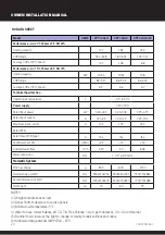
See section 3.2 Plumbing.

12�0 WINTERISATION PROCEDURE

WARNING. Isolate machine before opening! As heat pump embodies electrical and rotational 

equipment, it is recommended for your own safety that a competent person carries out the 

following procedure.

(Drain Down Procedure)

ALL MODELS

Objective

To provide frost protection

To eliminate corrosion problems

To inhibit electrical components

1.  Switch off electrical supply to heat pump.
2.  Remove external fuses and keep in safe place away 

from heat pump to prevent accidental operation of 
heat pump.

3.  Ensure water circulation pump is switched off.

4.  Drain water from heat pump by:
a) Drain valve if fitted.
b) Disconnecting pipework to and from heat pump.
c) Remove condenser drain down cover.
d) Flush through water circuit in heat pump by using 
CLEAN TAP WATER (NOT POOL WATER) via hose into 
outlet connection – run for 10 minutes minimum, use 
spray nozzle if available.
e) Allow to drain – fit plastic bags secured by elastic 
bands over water connections.
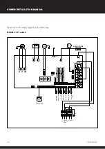
5.  Uncover electrical enclosure (page 13) and 

liberally spray interior of unit, with moisture repellant 
aerosol WD-40 or similar, reseal enclosure.

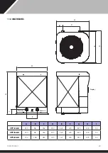
6.  If heat pump located outside, protect from weather 

by covering with VENTILATED cover. A bespoke 
cover is available. Do not use plastic sheet as 
condensation can occur within unit.

If this procedure is not adopted and frost or corrosion damage results 

then the warranty will become invalid.

Summary of Contents for VPT 12

Page 1: ...V PAC inverter heat pump VPT 12 16 22 Owner Installation Manual 1005759 iss 1...

Page 2: ...This appliance can be used by children from 8 years and above and persons with reduced physical sensory or mental capabilities or lack of experience and knowledge if they have been given supervision...

Page 3: ...ELECTRIC WIRING AND SUPPLY 11 4 2 CONNECTING THE HEAT PUMP TO THE POWER SUPPLY 12 4 3 RECOMMENDED ELECTRICAL INSTALLATION FOR CALOREX HEAT PUMP WITH SINGLE PHASE WATER PUMP 13 5 0 OPERATION OF THE HEA...

Page 4: ...nt is environmentally friendly but safety instructions must be strictly adhered to The WARNING sign denotes a hazard It calls attention to a procedure or practice which if not adhered to could result...

Page 5: ...not place obstructions that will block air flow near the inlet or outlet Do not use or store combustible gas or liquids near the heat pump The heating performance can be improved by insulating the fl...

Page 6: ...eat pump upright Do not lift the heat pump by the water inlet or outlet connections If this is done the titanium heat exchanger inside the heat pump could be damaged 2 2 ACCESSORIES These accessories...

Page 7: ...NS AND RANGE Air temperature operating range 5 43 C Heating temperature setting range 18 C 40 C Cooling temperature setting range 12 C 30 C 2 5 OPERATING MODES The heat pump has three modes Powerful m...

Page 8: ...bstructions are shown below The heat pump must be fixed by M10 bolts to a concrete base or mounting brackets These must be solid and fixed securely Brackets must be corrosion proof Do not block inlet...

Page 9: ...r fitted Non return valve Sanitiser or chemical dosing device If fitted Aux heater If fitted Filter Pump To waste for winterising drain down 100mm Condensate water to waste Spare port for winterising...

Page 10: ...drain or soak away 3 Inlet and outlet pipework must be supported to avoid excessive strain on the connections 4 Water quality must be maintained as follows 3 2 PLUMBING Supported pipework Water out W...

Page 11: ...g pool water should be bonded together using 10mm bonding cable This includes non electrical items such as metal filters pump strainer boxes heat exchangers steps and handrails It is highly recommende...

Page 12: ...in machine Cable clamp L3 N Fuses MCB Earthed Power Supply 400V 50Hz L3 N P1 P2 Power terminals Pump terminals Single phase Terminals in Heat Pump Electrics enclosure L2 L1 L2 L1 1 Remove these four s...

Page 13: ...N L Single phase Switched fuse isolator within 2m of heat pump and sized in accordance with datasheet Single phase supply to suit capacity Water pump more than 3 4 HP Single Phase Minimum 2 Pole N O...

Page 14: ...de indicator light Powerful mode indicator light Powerful Smart Silent M 88 88 Silent mode indicator light Power HEAT COOL Heating indicator light Timer on indicator light Timer off indicator light Co...

Page 15: ...or 5 seconds the heating mode lamp flashes and defrost starts When defrosting is exited the display returns to normal f Clock Setting Turn the heat pump off via the Press M to enter the clock settings...

Page 16: ...ings press and hold the Silent for 5 seconds and use the p and q to scroll through The first number that is flashing is the parameter code Press to return to main menu b Factory reset Press and hold t...

Page 17: ...f Improper operation may cause danger 8 0 TROUBLE SHOOTING COMMON FAULTS Requirements for service personnel Any person who is involved with working on or breaking into a refrigerant circuit should hol...

Page 18: ...ircuit breaker trips frequently If above solutions don t work please contact your installer with detailed information and your model number Don t try to repair it yourself 8 2 PROTECTION CODES These c...

Page 19: ...aust gas temperature alarm Er 15 Water inlet temperature sensor failure Er 16 Evaporator coil temperature sensor failure Er 18 Exhaust gas temperature sensor failure Er 19 DC fan motor error Er 20 Inv...

Page 20: ...current A 1 21 8 9 1 23 12 0 3 45 19 6 Maximum input current A 12 5 15 5 24 5 Rated RCD Rated Fuse MCB type C A tba tba tba Sound level at 10m dB A 29 30 30 Advised water flow m3 h 4 97 6 5 8 98 Wate...

Page 21: ...T1 T9 T10 T11 IN1 IN1 IN1 IN1 IN1 WIRE CONTROLLER Heat coil temp Cool coil temp OUT 1 OUT 2 OUT 3 OUT 4 OUT 5 OUT 6 OUT 7 U V W 4 WAY VALVE EEV 1 MF EGND N1 AC N1 Outlet water temp Ambient temp Retur...

Page 22: ...1 T9 T10 T11 IN1 IN1 IN1 IN1 IN1 WIRE CONTROLLER Heat coil temp Cool coil temp OUT 1 OUT 2 OUT 3 OUT 4 OUT 5 OUT 6 OUT 7 U V W 4 WAY VALVE EEV 1 MF EGND N1 AC N1 Outlet water temp Ambient temp Return...

Page 23: ...11 0 DIMENSIONS A B C D E F G H I VPT12 ALX 650 98 362 650 626 220 835 600 92 VPT16 ALX 650 98 362 650 626 220 835 600 92 VPT22 ALX 752 138 387 745 721 240 967 695 92 F I B C A E D H G Display Water i...

Page 24: ...ve To provide frost protection To eliminate corrosion problems To inhibit electrical components 1 Switch off electrical supply to heat pump 2 Remove external fuses and keep in safe place away from hea...

Page 25: ...he air flow to and from the machine is outside the specified limits If in doubt or if advice is required please contact the Dantherm Group UK Service Department by calling 44 0 1621 856 611 option 4 o...

Page 26: ...26 1005759 ISS 1 OWNER INSTALLATION MANUAL...

Page 27: ...27 1005759 ISS 1...

Page 28: ...Dantherm Ltd Unit 12 Galliford Road Maldon CM9 4XD United Kingdom 44 0 1621 856 611 sales uk dantherm com Calorex is a brand of danthermgroup com...

Reviews: