


Product User Manual
4
5
2. Product installation instructions
1.3 The structure of battery
Battery is made up by the electrode assembly, the positive terminal and
negative terminal, safety valve, the shell cover and the shell. Electrode group
consists of positive and negative electrode terminal and seperator (seperator
plays a barrier between the positive and negative electrode).The shell interi-
or is filled with the electrolyte. Safety valve on the shell cover can release the
battery internal pressure and prevent explosion.
2.1 Battery Requirements
1) Please read this instruction and other instructions carefully before using the battery.
2) Unless otherwise specified, the charging and discharging parameters of CALB lithium iron phosphate batteries series are
described as follows:
• Cut-off charging voltage for single battery: 3.65V (Switch off voltage for single battery charging: 3.8V. Once the cell voltage
rises to 3.8V, the charging current should be immediately cut off);
•
Cut-off charging voltage for N batteries in series: N × 3.65V (when the cell voltage rises to 3.65V, the charger should be able
to automatically change to constant voltage charging mode);
• The float status: cutoff charging voltage for single battery is set to 3.4V, cut-off voltage for N batteries charging in series is
N×3.4V, with a maximum voltage of 3.4V cut-off;
• Alarming discharging voltage for single battery: 2.8V (during the discharging process, when the cell voltage drops to 2.8V,
BMS will alarm, we recommend stopping discharging now);
• Cut-off discharging voltage for single battery: 2.5V (under -20
℃
condition,the cutoff voltage for battery discharging is 2.0V.);
3) CALB lithium-ion battery products shall be equipped with a special lithium battery management system and lithium battery charger
with mode of constant current and voltage limiting. For a few small-capacity batteries are used in series, you can also use lithium
batteries protection board of reliable performance;
4) In any case, terminal voltage of single cells must be monitored in real-time. Battery packs in series charging or discharging testing
without management system or protective board is forbidden, avoiding battery overcharge or over-discharge.
5) BMS used shall have function of insulation resistance detection, when the battery and BMS installation is complete, all protection
parameters would be the first to set. Be sure to confirm the battery power when setting the initial value of SOC;
6) Communication protocol must be determined between the BMS and charger and motor controller. Make sure of the signal butt
between BMS and charger and motor controller to ensure that the charger and motor controller is monitored in real-time by BMS
during charging or discharging, avoiding over-charging or over-discharging.
7) Except in special circumstances, fresh battery from factory is only 30% charged. Before BMS and charger is commissioned,
batteries are prohibited for long time use to avoid overcharging or over-discharging ;During battery use, we recommend charging
and discharging range between 10-90% DOD (according to the principle of low depth of charge and discharge);
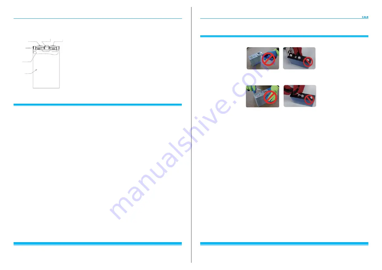
8) Screwing the battery terminal is forbidden without permission.
9) Damaging the battery safety valve is forbidden without permission.
9) Damaging the battery safety valve is forbidden without permission.
Positive Terminal
Negative Terminal
Safety Valve
Shell Cover
Electrode Assembly
Shell
Screwing the battery terminal is forbidden without permission.
Damaging the battery safety valve is forbidden without permission.
2.2 Power System Requirements
1) High-voltage main circuit and low voltage electrical circuit for battery pack shall be properly isolated. Use reliable DC air circuit
breakers and fast DC fuses to make sure the safety under high-voltage.
2) Do not separate the lead power cord from the battery of the pack to charge a low voltage electronics in car individually.
3) The cabinet holding the system must be equipped with lightning protection and anti-tampering measures.
4) When splitting the system, battery system power should be disconnected to make sure the system can against electric shock.
When the system is assembled, it must be ensure that joints between the power supply modules are connected correctly and
firmly.
2.3 Power Module layout requirements
1) Be cautious when integrating the battery into power system. Not only should you take full consideration of ventilation inside the
power module, but also take effective dust proof, waterproof, anti-snow, and anti-impact measures;
2) Take full consideration of the convenience of repair and maintenance when laying out the batteries.
3) Integrate battery modules into group according to the maximum possible number of cells that a individual BMS sub-module can
manage ablity.
4) Ensure high-pressure cables and wiring harnesses short and smooth when laying out the batteries and battery modules.
5) Because the drive motors and motor controllers are strong heating element, batteries should be layout away from them. When
batteries are near the motor, proper insulation measures shall be taken ;
6) When many batteries are laid out intensively, avoid the situation that adjacent terminal voltage of the battery packs is higher than
safe voltage to prevent dangerous electric shock during construction and maintenance.
7) If the system is lay out in a compute room, fireproof materials should be equipped on the walls, ceilings and walls, firefighting
equipment should be equipped. There should be no flammable, explosive, corrosive gases or article around the site.
2.4 Power Module Installation Requirements
Power module or battery shall be operated in accordance with relevant instructions;
1) After clamping, each battery group should be fixed into the power module properly with the terminals upward clamped .Placing the
battery on its side is not recommended , installing the battery upside down is prohibited ;
2) When clipping the power modules into group, make sure all flat washers, spring washers and nuts in readiness and tight.


