


001-0004-829 Rev00
Page 9 of 84
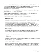
SMC Module Description
Top side reference
Fig. 2.1 SMC-GPRS Top Side
SMC-GPRS top side components:
1. Power
: Green LED indicating cell module power on.
2. DCD
: Red LED indicating Data Carrier Detect from cellular network.
3. RF (antenna)
: MMCX socket, primary antenna connection.
4. SIM:
SIM Card Slot (SIM card purchased separately).
5. GSM Cell Module
4
3
5
2
1
Summary of Contents for SMC-GPRS Series
Page 2: ...REVISION HISTORY Rev00 Released 10 06 2009 C Pollock...
Page 62: ...001 0004 829 Rev00 Page 62 of 84...
Page 63: ...001 0004 829 Rev00 Page 63 of 84...
Page 64: ...001 0004 829 Rev00 Page 64 of 84...
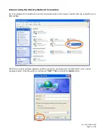
Page 65: ...001 0004 829 Rev00 Page 65 of 84 Configuring the Modem...
Page 66: ...001 0004 829 Rev00 Page 66 of 84 Create a Dial Up Networking DUN Connection...
Page 67: ...001 0004 829 Rev00 Page 67 of 84...
Page 68: ...001 0004 829 Rev00 Page 68 of 84...
Page 69: ...001 0004 829 Rev00 Page 69 of 84...
Page 70: ...001 0004 829 Rev00 Page 70 of 84...
Page 71: ...001 0004 829 Rev00 Page 71 of 84...
Page 72: ...001 0004 829 Rev00 Page 72 of 84...
Page 74: ...001 0004 829 Rev00 Page 74 of 84...
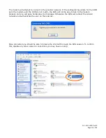
Page 75: ...001 0004 829 Rev00 Page 75 of 84 Choose the COM port to be connected to the modem...
Page 76: ...001 0004 829 Rev00 Page 76 of 84...
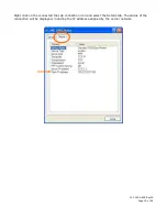
Page 77: ...001 0004 829 Rev00 Page 77 of 84 Configuring the Modem...
Page 79: ...001 0004 829 Rev00 Page 79 of 84...
Page 81: ...001 0004 829 Rev00 Page 81 of 84...
Page 82: ...001 0004 829 Rev00 Page 82 of 84...


