CADnetwork RenderCube User Manual Download Page 28

Chapter 2: Hardware information

4.

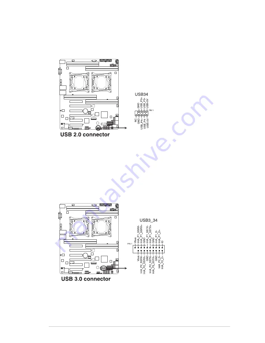
USB 2.0 connector (10-1 pin USB34)

These connectors are for USB 2.0 ports. Connect the USB module cables to

connectors USB56. These USB connectors comply with USB 2.0 specification that

supports up to 480 Mb/s connection speed.

5.

USB 3.0 connector (20-1 pin USB3_34)

This connector allows you to connect a USB 3.0 module for additional USB 3.0 front

or rear panel ports. With an installed USB 3.0 module, you can enjoy all the benefits of

USB 3.0 including faster data transfer speeds of up to 5Gbps, faster charging time for

USB-chargeable devices, optimized power efficiency, and backward compatibility with

USB 2.0.

Summary of Contents for RenderCube

Page 1: ...RenderCube Rack Mainboard Manual...

Page 2: ...it into the chassis in the correct orientation The edge with external ports goes to the rear part of the chassis as indicated in the image below 2 2 2 Screw holes Place nine 9 screws into the holes in...

Page 3: ...Chapter 2 Hardware information 2 2 3 Motherboard layout RenderCube Rack...

Page 4: ...e motherboard 2 3 Central Processing Unit CPU The motherboard comes with a surface mount LGA 2011 3 Socket designed for the Intel Xeon E5 2600 v3 processor family Before installing the CPU ensure that...

Page 5: ...from the retention tab B then gently lift the load lever C To prevent damage to the socket pins do not remove the PnP cap unless you are installing a CPU 3 Press the right load lever with your thumb...

Page 6: ...the load lever into the retention tab The CPU fits in only one correct orientation DO NOT force the CPU into the socket to prevent bending the CPU pins on the socket 6 Get the CPU 7 Align and position...

Page 7: ...tucked securely under the lever J then insert the right load lever under the retention tab K The PnP cap pops out of the load plate when the right load lever is inserted into the retention tab 11 Push...

Page 8: ...Thermal Interface Material is toxic and inedible DO NOT eat it If it gets into your eyes or touches your skin wash it off immediately and seek professional medical help Ensure that the Thermal Interf...

Page 9: ...kets 2 4 2 Memory Configurations You may install 4 GB 8 GB 16 GB and 32 GB RDIMMs or 32 GB and 64 GB LR DIMMs into the DIMM sockets using the memory configurations in this section When installing DIMM...

Page 10: ...Dual CPU configuration You can refer to the following recommended memory population for a dual CPU configuration Single CPU configuration You can refer to the following recommended memory population...

Page 11: ...M slot key 1 Press the retaining clip outward to unlock the DIMM 2 Remove the DIMM from the socket Removing a DIMM from a single clip DIMM socket To install two or more DIMMs refer to the user guide b...

Page 12: ...he slot 5 Secure the card to the chassis with the screw you removed earlier 6 Replace the system cover 2 5 2 Configuring an expansion card After installing the expansion card configure it by adjusting...

Page 13: ...nts Standard Interrupt assignments 2 5 4 PCI Express x16 slot x16 link The onboard PCIE3 and PCIE5 slots provides one x16 Gen3 link to CPU1 and auto switches to x8 link if PCIE4 PCIE6 is occupied This...

Page 14: ...en3 link 3 PCIE3 PCI E x16 x16 Gen3 link Auto switch to x8 Link if slot 4 is occupied 4 PCIE4 PCI E x8 x8 Gen3 link 5 PCIE5 PCI E x16 x16 Gen3 link Auto switch to x8 Link if slot 6 is occupied 6 PCIE6...

Page 15: ...an optional ASMB8 series management board on your motherboard 3 Insert the LAN cable plug to the LAN port 3 dedicated LAN or LAN port shared LAN for server management 1 Locate the Baseboard Managemen...

Page 16: ...agement Controller is available to RenderCube Rack SKU only 2 6 Onboard LEDs 1 Standby Power LED SB_PWR1 The motherboard comes with a standby power LED The green LED lights up to indicate that the sys...

Page 17: ...ERR_CPU2 The CPU warning LEDs light up to indicate failure on either CPU1 CPU2 or both 4 CATT LED CATTERR_LED1 The CATT LED indicates that the system has experienced a fatal or catastrophic error and...

Page 18: ...Hardware information 5 Q Code LEDs LED1 The Q Code LED provides a 2 digit display that shows the status of your system Refer to the Q Code table of this user guide for more information about the 2 di...

Page 19: ...Progress QPI initialization AA MRC Progress QPI initialization AB MRC Progress QPI initialization AC MRC Progress QPI initialization AD MRC Progress QPI initialization AE MRC Progress QPI initializati...

Page 20: ...umeration 96 Progress PCI Bus Enumeration 97 Progress Console outout connect event 98 Progress Console input connect event 99 Progress AMI Super IO start 9A Progress AMI USB Driver Init 9B Progress AM...

Page 21: ...the power cord 2 Move the jumper cap from the default pins 1 2 to pins 2 3 Keep the cap on pins 2 3 for about 5 to 10 seconds then move the cap back to pins 1 2 3 Plug the power cord and turn ON the...

Page 22: ...r allows you to enable or disable the onboard VGA controller Set to pins 1 2 to activate the VGA feature 3 LAN controller setting 3 pin LAN_SW1 LAN_SW2 These jumpers allow you to enable or disable the...

Page 23: ...ME_RCVR1 This jumper allows you to force Intel Management Engine ME boot from recovery mode when ME becomes corrupted 5 DDR4 thermal event setting 3 pin DIMMTRIP1 This jumper allows you to enable or d...

Page 24: ...the third party software LSI MegaRAID software RAID Configuration Utility otherwise place the jumper caps to pins 2 3 to use the Intel Rapid Storage Technology enterprise SATA Option ROM Utility 7 PMB...

Page 25: ...t is for a VGA monitor or other VGA compatible devices 6 USB 3 0 ports 1 and 2 These two 4 pin Universal Serial Bus USB ports are available for connecting USB 3 0 devices LAN port LED indications Acti...

Page 26: ...onnectors 1 Serial ATA 6 0 Gbps connectors 7 pin SATA1 SATA2 SATA3 SATA4 SATA5 SATA6 Light Blue 7 pin SSATA1 SSATA2 SSATA3 Gray SSATA4 Light Gray Supported by the Intel 612 Series chipset this connect...

Page 27: ...nnect SMBus System Management Bus to the PSU power supply unit to read PSU information Devices communicate with an SMBus host and or other SMBus devices using the SMBus interface This connector functi...

Page 28: ...orts up to 480 Mb s connection speed 5 USB 3 0 connector 20 1 pin USB3_34 This connector allows you to connect a USB 3 0 module for additional USB 3 0 front or rear panel ports With an installed USB 3...

Page 29: ...d pin of the connector DO NOT forget to connect the fan cables to the fan connectors Insufficient air flow inside the system may damage the motherboard components These are not jumpers DO NOT place ju...

Page 30: ...nector 20 1 pin TPM1 This connector supports a Trusted Platform Module TPM system which can securely store keys digital certificates passwords and data A TPM system also helps enhance network security...

Page 31: ...when using 85W or below CPU otherwise the system will not boot up DO NOT forget to connect the 24 8 8 pin power plugs when using 105W or above CPU otherwise the system will not boot up Use of a PSU w...

Page 32: ...PEAKER This 4 pin connector is for the chassis mounted system warning speaker The speaker allows you to hear system beeps and warnings 4 Hard disk drive activity LED 2 pin HDD LED This 2 pin connector...

Page 33: ...LINKACTLED LAN2_LINKACTLED These connectors are for Gigabit LAN activity LEDs on the front panel 3 Locator LED 2 pin LOCATORLED1 LOCATORLED2 These connectors are for the locator LED1 and LED2 on the f...

Page 34: ...the SATA or SAS add on card causes the front panel LED to light up 13 Chassis Intrusion 2 pin INTRUSION1 These leads are for the intrusion detection feature for chassis with intrusion sensor or micro...

Reviews: