


NX-480 Wireless Motion Sensor
Page 5
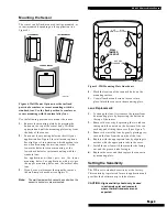
Figure 7. PIR Components, Battery Locations, &
Tamper Switch
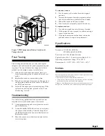
Final Testing
Final testing should be done to verify radio signal
integrity and confirm control panel programming and
response. The actual transmitter range can be deter-
mined by performing a sensor test as follows:
1.
After the sensor has been mounted, remove it
from its mounting plate to activate the walk test
mode.
2.
Replace the sensor in its mounting plate.
3.
Place the control panel in test mode. Move across
the detection pattern until the sensor’s LED turns
on. STOP your motion.
4.
Listen for the appropriate system response. If the
system does not respond, proceed to the “Trou-
bleshooting “section.
Troubleshooting
Use the following guidelines if the system does not
respond correctly when the sensor is activated.
■
Check programming and re-program sensor into
panel if necessary.
■
Use an RF Sniffer (NX-468) test tool to verify that
the sensor is transmitting. Constant beeps from
the RF Sniffer indicate a runaway (faulty) sensor.
Replace the sensor.
■
Move the sensor to another location and test for
correct response.
To relocate a sensor:
1.
Test the sensor a few inches from the original
position.
2.
Increase the distance from the original position
and retest until an acceptable location is found.
3.
Mount the sensor in the new location.
4.
If no location is acceptable, replace the sensor.
To replace a sensor:
1.
Test a known good sensor at the same location.
2.
If the system does not respond, avoid mounting a
sensor at that location.
3.
If the replacement sensor functions, return the
problem sensor for repair or replacement.
Specifications
Frequency: 319.5 MHz. (NX-480)
433 MHz. (60-639-43-EUR)
Power source: 2 AA alkaline batteries
Typical battery life: 3 - 4 years (not verified by U.L.)
Operating temperature range: 32° to 120° F
Dimensions: L = 2.875” X W = 2.375” X H = 1.875”
Notices
These devices comply with part 15 of the FCC rules. Operation is sub-
ject to the following two conditions:
1. These devices may not cause harmful interference.
2. These devices must accept any interference received, including
interference that may cause undesired operation.
Changes or modifications not expressly approved by Interactive Tech-
nologies, Inc. can void the users’ authority to operate the equipment.
8362G02A.DS4
MOUNTING
PLATE
SENSOR
BODY
PIR
COVER
LENS
TAMPER
SWITCH
PWB
COVER
TABS


