background image

3-1

Revision MA2005-7

M16 Microphone Amplifier

3

The M16 Microphone Amplifier

3.1

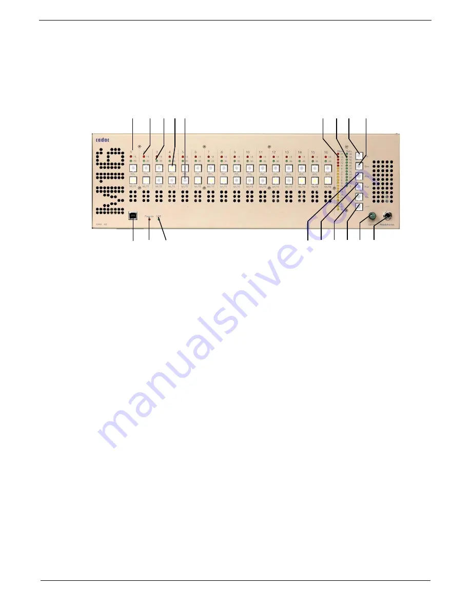
M16 Front panel

1. Channel Number
2. Signal Overload Indicator
3. Signal Present Indicator
4. PFL Switch
5. Mute Switch
6. Headphone Socket
7. Headphone Level Control
8. PFL Level Meter
9. Channel Gain
10.Gain Increment Switch
11.Gain Decrement Switch
12.Polarity Reverse 
13.Pad Switch
14.Phantom Power Switch
15.High Pass Filter Switch
16.Remote Indicator
17.USB Indicator
18.USB port

FIG 3-1.  M16 front panel layout

1       2     3   4   5                                                                  8     9   10     11         

16     17                                                                  12   13  14   15   7     6

18

Summary of Contents for M16

Page 1: ...Remote Controlled Microphone Amplifier M16...

Page 2: ...Remote Controlled Microphone Amplifier Installation User Manual M16...

Page 3: ...16 Microphone Amplifier 3 1 3 1 M16 Front panel 3 1 3 2 M16 Rear Panel 3 2 3 3 Connecting up your M16 3 3 3 3 1 Mains power 3 3 3 3 2 Ground stud 3 3 3 3 3 Audio Connections 3 3 3 3 4 Power On 3 4 3 4...

Page 4: ...guring the system 4 5 4 10 2 Control Menu 4 7 4 10 3 Naming M16 units 4 7 4 10 4 Naming M16 channels 4 8 4 10 5 System Integrity 4 9 4 11 RM16 Meters 4 10 4 11 1 Channel Mute indication 4 10 4 11 2 Me...

Page 5: ...th many hundreds of CADAC consoles working day in day out in many of the world s premier venues and tours For over 30 years CADAC has been receiving high praise for its very natural sounding microphon...

Page 6: ...r remote control options Up to 32 x M16 units can be connected to one control system Audio interfaces directly with the CADAC D16 16 x 16 Digital Mix Matrix via dedicated buss link connectors Designed...

Page 7: ...ntertainment lighting control apparatus for professional use Part 1 Emissions BS EN 55103 2 1997 Electromagnetic Compatibility Product family standard for audio video audio visual and entertainment li...

Page 8: ...vi M16 Microphone Amplifier Revision MA2005 7...

Page 9: ...e risk of fire use only the recommended fuse type as in dicated in this manual and on the M16 Do not short circuit the fuse holder Before changing the fuse always switch off the unit and remove the IE...

Page 10: ...re to align it properly The guide arm of the fuse holder slots into the power connector assembly Once in place push the fuse holder home and confirm that it is fully seated 1 3 Fuse Types Live 90v 250...

Page 11: ...use this apparatus near water Do not block any of the ventilation openings Do not install near any heat sources Do not install near naked flames Protect the mains cable from being stressed or pinched...

Page 12: ...1 4 M16 Microphone Amplifier Revision MA2005 7...

Page 13: ...safely include additional M16 specific items The M16 packaging contains 1 x M16 1 x set of rack mounting ears fitting screws 1 x IEC mains cable either fitted with UK or US style plug or unwired depe...

Page 14: ...e 1 1 Mains Cable Obtain professional advice from a qualified electrician if unsure 2 3 Cleaning Before cleaning the M16 make sure the unit is switched off and the mains plug is removed from the socke...

Page 15: ...or 4 PFL Switch 5 Mute Switch 6 Headphone Socket 7 Headphone Level Control 8 PFL Level Meter 9 Channel Gain 10 Gain Increment Switch 11 Gain Decrement Switch 12 Polarity Reverse 13 Pad Switch 14 Phant...

Page 16: ...6 Word Clock Input Output Selector Switch 7 Fibre Optic Output Connector Tx for MADI Output 8 Fibre Optic Input Connector Rx Not Used 9 64 32 56 28 MADI Protocol Switch 10 96kHz 48kHz Sample Rate Swit...

Page 17: ...arth Conductors which can reduce induced noise within audio ca bling by up to 80 if used correctly System wiring and grounding techniques fall well outside the scope of this User Manual however there...

Page 18: ...re accessed via the front panel Channel Control Section see 3 4 4 Channel Control Section 3 4 1 Channel LED indicators LEDs are provided on each channel for visual indication of signal present and sig...

Page 19: ...ction Using the bank of PFL switches select the first channel that requires the parameter change s Keeping this switch pressed select the other channels that are required to be simultaneously controll...

Page 20: ...p of channels Gain is controlled in 5dB steps via the Increment and Decrement switches to the right of the Gain Indicator NOTE When multiple channels are selected the x indicator at the bottom of the...

Page 21: ...e headphones The headphone circuitry is designed to drive a load of 150 ohms up wards Headphone impedances below 150 ohms can still be used however the audio level will be reduced It is possible to bu...

Page 22: ...ut section It is not possible to mute channels on the MADI output Connect the other end of the optical cable to the receiving device 3 6 2 MADI Setup The M16 supports both 56 channel MADI and 64 chann...

Page 23: ...e the CLK IN OUT momentary button located next to the Word Clock BNC connector to select whether Word Clock is externally sourced IN or internally generated OUT LED indication provides confirmation of...

Page 24: ...3 10 M16 Microphone Amplifier Revision MA2005 7...

Page 25: ...e M16 Remote Controlled Microphone Amplifier The RM16 provides full control over every feature in the Channel Control Section see section 3 4 4 Channel Control Section while also providing the ability...

Page 26: ...Screen 9 Control Soft Keys 4 5 Rear Panel 1 DC Power Connector 2 Remote Control In Connector 3 Remote Control Out Connector 4 6 Connections 4 6 1 RM16 Power Power for the RM16 is supplied via an exter...

Page 27: ...al locking collar to avoid inad vertently removing it from the RM16 4 6 2 Remote Control Communications Backbone Communications interconnection between RM16 and M16 plus oth er CADAC rack units is mad...

Page 28: ...nnec tors connect one end to the OUT XLR 3M connector located on the rear panel of the RM16 Connect the other end of the communications cable into the RS 485 IN XLR 3F connector located on the rear pa...

Page 29: ...M16 Root menu see FIG 4 7 RM16 root menu select Edit by pressing the associated illuminated button below the menu Select System from the Edit menu Select Enumerate from the System Configuration and Te...

Page 30: ...4 6 M16 Microphone Amplifier Revision MA2005 7 NOTE If in a sub menu and no buttons on the RM16 are pressed for a period of 30 seconds the Control Menu will return to the Root menu...

Page 31: ...is stored in EEPROM memory within the M16 itself therefore the rack name will be recalled when interrogated via the RM16 Each M16 is shipped from the factory with a default rack name of CADAC M16 Sys...

Page 32: ...each channel Chan 1 Chan 2 etc however these may be over written Select the Rack containing the channels that require naming by pressing the Rack buttons located beneath the menu screen This will incr...

Page 33: ...he RM16 menu display This is a very useful feature as these units could be some distance apart To confirm correct operation over the communications backbone M16 Check that the red Remote indicator on...

Page 34: ...sely a theatrical performance where there is an importance for audio equipment to emit as little light as possi ble From the RM16 root menu see FIG 4 7 RM16 root menu select Edit by pressing the assoc...

Page 35: ...sole it would be common practice for the console operator to simply mute a particular channel on the mixing console rather than on the M16 However if muting an M16 channel via the RM16 is required th...

Page 36: ...ps occurring 4 18 High Pass Filter To enable the selected channel s High Pass Filter to remove any low frequency rumble press the High Pass Filter switch Once enabled the switch will illuminate To dea...

Page 37: ...3 1kHz Crosstalk 10dB gain input level 0dBu 80dB at 10kHz Phantom power 48VDC 14mA per channel High Pass filter 3dB frequency 60Hz Slope 12dB per octave Analogue outputs all outputs are electronically...

Page 38: ...z Power Consumption 110VA Operating Temperature 0 to 40 C Dimensions in mm WxHxD 3RU x 420mm inc projections Unit weight 8kG 18lbs Average shipping weight 12kG 26lbs Accessories Operation manual USB c...

Page 39: ...Pin 4 Output 2 4 Audio Pin 23 Output 2 4 Audio Pin 5 Output 2 5 Audio Pin 24 Output 2 5 Audio Pin 6 Output 2 6 Audio Pin 25 Output 2 6 Audio Pin 7 Output 2 7 Audio Pin 26 Output 2 7 Audio Pin 8 Outpu...

Page 40: ...put 3 7 Audio Pin 8 Output 3 8 Audio Pin 27 Output 3 8 Audio Pin 9 Output 3 9 Audio Pin 28 Output 3 9 Audio Pin 10 Output 3 10 Audio Pin 29 Output 3 10 Audio Pin 11 Output 3 11 Audio Pin 30 Output 3 1...

Page 41: ...to ensure compliance with the European EMCD Electro Magnetic Compliance Directive BSEN55103 1 Emissions and BSEN55103 2 Immunity Common Bonding means a single conductive structure for all reference s...

Page 42: ...at neither SAM Configuration nor Sound Automation Manager is run ning on the system If either of these applications is active then it must be closed NOTE Prior to updating the M16 Flash Memory with ne...

Page 43: ...ng Utility Make sure that the M16 is switched on and the USB cable is con nected to both computer and M16 Click on the Start button on the Windows Taskbar Select All Programs Sound Automation Manager...

Page 44: ...ighlight the unit that re quires updating by clicking over the Unit ID number This will high light the unit and display the unit serial number within the File box Click on the Load File button and sel...

Page 45: ...OVE POWER OR ANY CONNECTIONS OTHERWISE THE FIRMWARE UPDATE WILL BE INTERRUPTED AND THE M16 MAY NO LONGER OPERATE IF THIS HAPPENS THE UNIT WILL NEED TO BE RETURNED TO CADAC OR YOUR LOCAL DISTRIBUTOR On...

Page 46: ...bers will be displayed for both the M16 control software and the MADI firmware The 18dB LEDs indicate the MADI firmware version while the 36dB LEDs indicate the control firmware version In both cases...

Page 47: ...APP 9 Revision MA2005 7 M16 Microphone Amplifier...

Page 48: ...APP 10 M16 Microphone Amplifier Revision MA2005 7...

Page 49: ...and is provided on a pre paid RTB return to base basis This warranty will not reimburse nor cover damage sustained as a result of modifications that have been made to the product without the prior wr...

Page 50: ...Warranty 2 M16 Microphone Amplifier Revision MA2005 7...

Page 51: ...onnections 3 3 C Changing the fuse 1 1 Channel Control Section 3 5 Channel Control Section Parameters 3 6 Channel LED indicators 3 4 Channel Number 3 1 Channel Selection 4 11 Cleaning 2 2 Clearing mul...

Page 52: ...ncrement and Decrement Switches Inc Dec 3 6 Inputs 3 3 Installation 2 2 M M16 selection 4 10 MADI 3 4 MADI Channel Selection 3 8 MADI Output 3 7 MADI Setup 3 8 Mains Cable 1 1 Mains Inlet and Power sw...

Page 53: ...ntrol of the M16 4 1 Remote control options 4 1 Remote Indicator 3 1 RM16 configuration 4 5 RM16 Front Panel 4 2 RM16 Meters 4 10 RM16 Power 4 2 RM16 Rear Panel 4 2 RS 485 Communications Protocol 4 1...

Page 54: ...one Amplifier Revision MA2005 7 U Unpacking 2 1 Updating M16 Firmware APP 4 USB Indicator 3 1 USB ReProgramming Utility APP 4 W Word Clock 3 2 3 9 Word Clock BNC Connector 3 2 Word Clock Input Output...

Page 55: ...ail info cadac sound com web http www cadac sound com While every effort has been taken to ensure the accuracy of the contents in this manual CADAC equipment is being subject to continuous development...

Reviews: