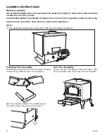
3. Assembly Instructions
•
PLEASE NOTE:
Please ensure all protective packaging and plastic are removed from the appliance before use.
To assemble the four feet(I) onto the appliance, use a screw driver and the four screws supplied to fix the feet into position.
•
Before using the Stove it is necessary to fit the hose and an approved 2,8kPa pressure regulator. The hose and regulator are supplied with
the 2 Plate Stove and comply with SANS 1156-2 / BS3212 and SANS 1237 respectively as per regulations.
The hose length should be no less than 800 mm and shall not exceed 2.0 m, check the expiry date on the hose and replace when necessary.
Do not twist or pinch the hose. Ensure that
it is routed away from the Stove Body so as
deterioration
to prevent
/ damage to the
hose caused by heat.
Fit the one end of the low-pressure hose
onto the regulator nozzle and the other end
onto the stove nozzle, by pushing on firmly
until fully seated against the back shoulder
on the nozzle (See Fig. 3)
Ensure that the connections are made
securely and do not allow gas to leak.
Ensure that the appliance valves are in the
off position by turning the knobs (E) fully
.
clockwise to the stop (See Fig. 4)
Control
Knob
Nozzle (H)
Hose
Stove Body
4. Fitting and Changing the Gas Cylinder
Before connecting the appliance to a gas cylinder, ensure that the rubber seal on the Regulator is in position and in good condition (See Fig.1).
Carry out this check each time you fit the appliance to a gas cylinder.
Blow out any dust from the cylinder opening to prevent possible blockage of the jet.
Ensure that the appliance valves are in the off position by turning the knobs fully clockwise to their stop (See Fig. 4)
Ensure that the gas cylinder is fitted or changed in a well-ventilated location, preferably outdoors, away from any source of ignition, such as naked
flames and away from other people.
Make sure that the gas cylinder is kept upright at all times, connect to the cylinder by screwing on hand tight until fully engaged.
Ensure that a complete gas seal has been made (check for the smell of gas around the connection joint). If there is a leak on your appliance
(smell of gas), take it outside immediately into a well-ventilated flame free location where the leak may be detected and stopped. To check for leaks
on your appliance, do it outside using warm soapy water only, which is applied to the joints and connections of the appliance. A formation of bubbles
will indicate the gas leak. Do not check for leaks with a naked flame.
If you cannot rectify the gas leak do not use the appliance, contact your local CADAC stockist for assistance.
CADAC gas cylinder valves must only be repaired by an authorised CADAC service centre or dealer.
When changing a gas cylinder firstly close the cylinder valve (if fitted) and then the appliance valve, making sure the flame is extinguished, unscrew
the regulator. Re-fit the regulator to a full cylinder following the same precautions as described above.
5.
sing the Appliance
U
The appliance is designed for use with cooking vessels of not less than 180mm in diameter and not greater than 250mm in diameter.
After lighting, do not move the gas cylinder and the appliance around, as liquefied gas may enter the appliance from the gas cylinder, causing it to
flare (large yellow flames).
Always operate the appliance on a firm level surface with the gas cylinder in an upright position.
Lighting the Appliance using the piezo
Turn the control knob clockwise to the 'OFF' position.
Turn the gas supply 'ON' at the cylinder.
Push down the control knob and keep pressing whilst turning anti-clockwise to the '
' position. This should light the burner. If not, repeat
Ignition
this process.
When the burner is lit, keep the control knob pressed for a few seconds, then release it.
If the burner does not stay alight, repeat steps 3 and 4. Adjust the heat by turning the knob to the 'High/Low' position.
To turn the stove 'OFF', turn the cylinder valve to the 'OFF' position and then turn the control knob on the appliance clockwise to the 'OFF'
position.
If the burner fails to ignite within 10 seconds, turn the control knob off (clockwise). Wait three minutes before attempting to re-light
Warning
with ignition sequence.
Lighting the Appliance with a match
To light the appliance light a match or barbecue lighter, turn on the appliance valve after connecting to and opening the cylinder valve, by turning the
control knob (E) in an anti-clockwise direction. Light the appliance burner (B1 & B2)
Use the control knob to adjust the flame intensity to the desired level by turning the knob clockwise to decrease the flame and anti clockwise to
increase it. (See Fig. 4)
After use, first close valve on gas cylinder. When the flame has extinguished close the valve on the appliance by turning knob fully clockwise.
Using the Air-Intake Adjuste
r
Depending on where the appliance is operated in the country, it may be necessary to set the air-intake adjuster.
To obtain a blue flame, adjust the air-intake adjuster by rotating it clockwise or anticlockwise until the desired flame is obtained.
Both burners are fitted with an air-intake adjuster.
Fig. 3
Fig. 4
Hose Clamp
6. General Maintenance
This appliance does not require scheduled maintenance.
It is dangerous to use an appliance with a cracked or perished seal and / or tubing. Inspect
both seals and tubing regularly and replace if they are not in order, before using the appliance.
If the appliance was in use, it will be hot. Allow to cool sufficiently before attempting any
maintenance.
The Stoves are fitted with jets to regulate the correct amount of gas.
Should the hole in the Jet become blocked this may result in a small flame or no flame at all.
Do not attempt to clean the jet with a pin or other such device as this may damage the orifice,
which could make the appliance unsafe.
Replacing a blocked jet:
Ensure that the cylinder valve is closed, then disconnect the appliance from the gas cylinder.
Remove the Potstands from the stove body.
Remove the Retaining Pin and Spring holding the Burner (B1 & B2) in position
Unscrew the blocked jet with a suitable spanner and replace it with a new jet.
Do not over tighten as this may damage the Jet. To re-assemble, reverse the above procedure.
Do not use pliers on the jet as this may damage the jet making it unusable or impossible to remove.
Replacement of hose:
Fitting of a hose is described in Section 3.
Burner
Retaining Clip
Spring
Stove Body
Fig. 5