25
Step
No.
Description
Picture
7
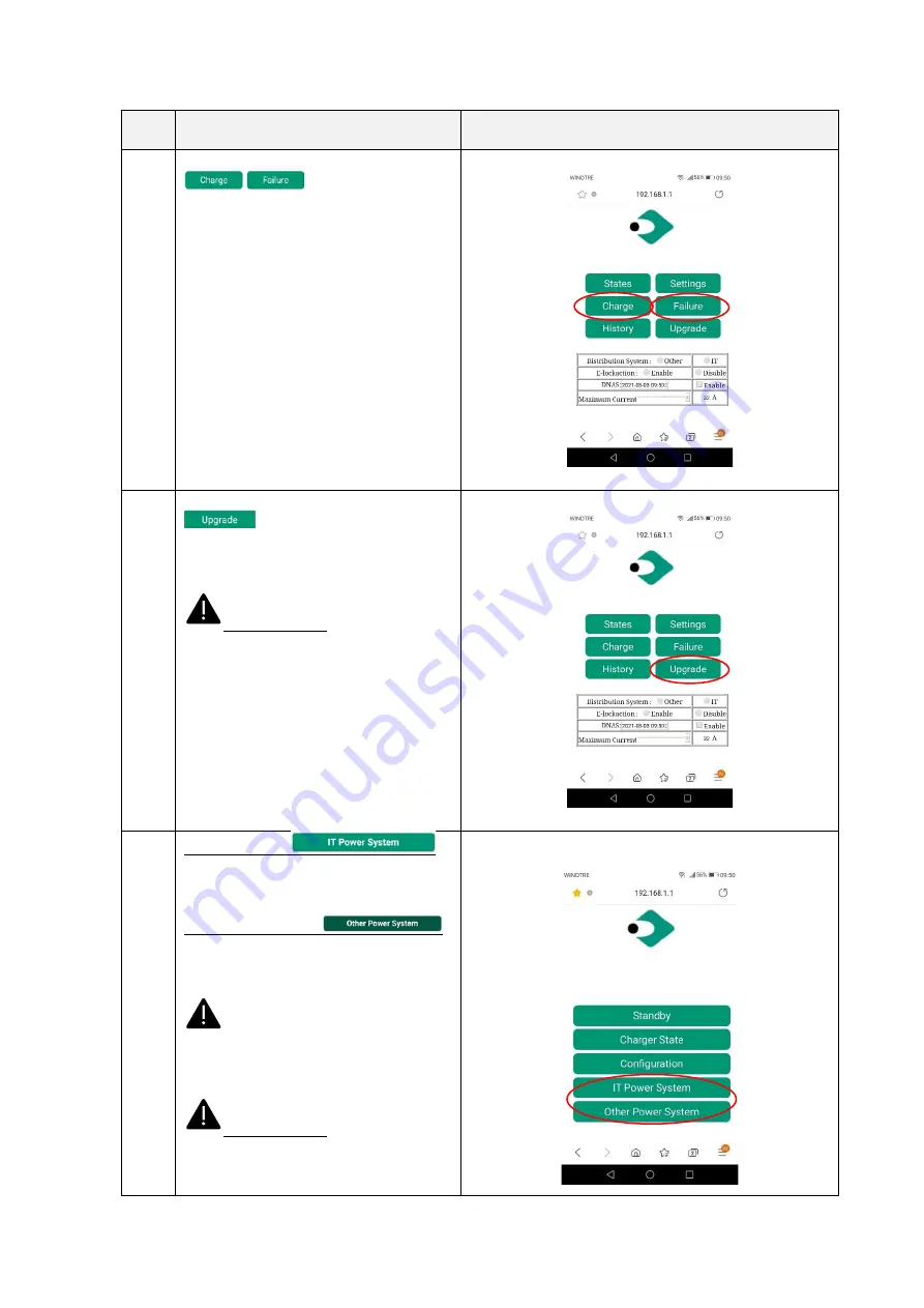
Clicking on the “
Charge
”
or “Failure”
buttons the user can
respectively access the charge report and
the failure report of the device
8
Clicking on the “Upgrade”
button
the user can upgrade the
system (see chapter 10 for details)
Important note
: these parameters
shall be configured by qualified personnel
only
10
IT Power system
this button enables the charger to be
supplied by IT power network systems
Other Power systems
this button enables the charger to be
supplied by TT or TN power network
systems
The selected power system is
indicated by the different colour of the
button after the selection
Important note
: these parameters
shall be configured by qualified personnel
only