background image


Manual 

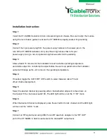
Installation Instruction: 

Step 1 

Install the CT-SAMM modulator into its corresponding rack chassis. Be sure to align the module 
using the rack chassis guides to ensure the CT-SAMM is properly seated  for grounding. 

Step 2 

Connect the 3-pin power plug from the power supply harness to the power jack in the               
rear of the CT-SAMM modulator. Only use the wiring harness that is for your                            
power supply. Using a non-compliant wiring harness will void the warranty. 

Step 3 

Allow at least 15 minutes for the modulator to reach a stable operating temperature                  
and stable output. Do not attempt to adjust before the warm up period since the modulator 
output will change as the unit comes to the operating temperature. 

Step 4 

If needed, toggle the CATV/VHF UHF switch to select between cable TV and                             
off-air channel assignment. 

Step 5 

Select the desired channel by pressing either channel button adjacent to the arrows on  
front panel. If the channel exceeds 100, The LED light will be on at the “+100 “ mark. 


Step 6 


When the desired channel is displayed, press the set button to lock channel and the LED light 
will be on at the “LOCK ” mark. 

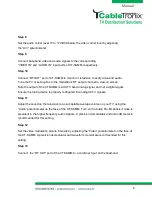
Step 7 

Connect an RF signal meter using dBmV or an RF spectrum analyzer to the “RF OUT”                  
port of the CT-SAMM to balance and ensure the desired RF output level. 


Summary of Contents for CT-SAMM

Page 1: ...Manual CT SAMM User Manual ...

Page 2: ...deg Group Delay 75 ns Hum Ratio 60dB RF Output Channels CATV 2 135 UHF 14 78 Output Level 45dBmV min Level Control Range 12 dBmV Adjustable A V Ratio Control 11 dB to 18 dB Adjustable Visual Frequency Stability 5 KHz Aural Carrier Offset 4 5 MHz Aural Carrier Stability 5 KHz Spurious Outputs 60dBc C N Ratio in band 60dB Out of Band Noise 78dBc Audio Input Level 0 5Vp p 25 KHz Deviation Input Imped...

Page 3: ...ting temperature and stable output Do not attempt to adjust before the warm up period since the modulator output will change as the unit comes to the operating temperature Step 4 If needed toggle the CATV VHF UHF switch to select between cable TV and off air channel assignment Step 5 Select the desired channel by pressing either channel button adjacent to the arrows on front panel If the channel e...

Page 4: ... and not a digital signal Ensure the tuning device is properly configured for analog CATV signals Step 11 Adjust the sound on the television to an acceptable average volume on your TV using the Audio potentiometer on the face of the CT SAMM Turn on the Audio Pre Emphasis if noise is prevalent in the higher frequency audio signals A precision demodulator and audio dB meter is recommended for this s...

Page 5: ... any hardware Repaired products shall carry the same amount of outstanding warranty as from original purchase Any claim under the warranty must include dated proof of purchase or invoice In any event the Company s liability for defective hardware is limited to repairing or replacing the hardware This warranty is contingent upon proper use of the hardware by Original Purchaser and does not cover if...

Page 6: ...bove exclusion applies to you This warranty allocates risks of product failure between Original Purchaser and the Company The Company s hardware pricing reflects this allocation of risk and the limitations of liability contained in this warranty The warranty set forth above is in lieu of all other express warranties whether oral or written The agents employees distributors and dealers of the Compa...

Reviews: