background image

NETWORK CONNECTIONS

Page 3 - 9

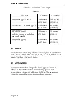
Table 3-4. Maximum Allowable Attenuation

3.6

IMPEDANCE 

The characteristic impedance for UTP cable is 100 ohms 

±

15%. For 

STP cable, the characteristic impedance is 150 ohms 

±

10%.

3.7

CROSSTALK

Is caused by signal coupling between the different cable pairs 
contained within a multi-pair cable bundle. In shielded pair cables, 
the effects of crosstalk are minimized.

3.8

NOISE

Can be caused by either crosstalk or externally induced impulses. 
If noise induced errors are suspected, it may be necessary to re-
route cabling away from potential noise sources (motors, 
switching equipment, high current equipment), or to ensure that 
the electrical wiring in the area is properly wired and grounded.

WARNING:

 It is the responsibility of the person who sells the 

system of which the adapter will be a part to ensure that the total 
system meets allowed limits of conducted and radiated emissions.

Table 2: 

Cable Type

at 4 Mbps

at 16 Mbps

STP (IBM Types 1 and 2

22 dB/Km

45 dB/Km

Voice Grade UTP (IBM Type 3)

56 dB/Km

131 dB/Km

STP (IBM Types 6 and 9)

33 dB/Km

66 dB/Km

Summary of Contents for T2015

Page 1: ...T2015 TOKEN RING NETWORK ADAPTER INSTALLATION GUIDE ...

Page 2: ...P N 9030354 03 March 1994 35 Industrial Way P O Box 5005 Rochester New Hampshire 03867 0505 ...

Page 3: ...NUAL OR THE INFORMATION CONTAINED IN IT EVEN IF CABLETRON SYSTEMS HAS BEEN ADVISED OF KNOWN OR SHOULD HAVE KNOWN THE POSSIBILITY OF SUCH DAMAGES Copyright August 1993 Cabletron Systems Inc 35 Industrial Way P O Box 5005 Rochester NH 03867 0505 All Rights Reserved Printed in the United States of America Order Number 9030354 02 August 93 LANVIEW and Remote LANVIEW Windows are registered trademarks a...

Page 4: ...perator s manual may cause harmful interference to radio communications Operation of this equipment in a residential area is likely to cause interference in which case the user will be required to correct the interference at his own expense WARNING Changes or modifications made to this device which are not expressly approved by the party responsible for compliance could void the user s authority t...

Page 5: ...RMS OF THIS AGREEMENT PROMPTLY RETURN THE UNUSED PRODUCT TO THE PLACE OF PURCHASE FOR A FULL REFUND CABLETRON SOFTWARE PROGRAM LICENSE 1 LICENSE You have the right to use only the one 1 copy of the Program provided in this package subject to the terms and conditions of this License Agreement 2 OTHER RESTRICTIONS You may not reverse engineer decompile or disassemble the Program 3 APPLICABLE LAW Thi...

Page 6: ...ATION OF LIABILITY FOR CONSEQUENTIAL OR INCIDENTAL DAMAGES OR IN THE DURATION OR LIMITATION OF IMPLIED WARRANTIES IN SOME INSTANCES THE ABOVE LIMITATIONS AND EXCLUSIONS MAY NOT APPLY TO YOU UNITED STATES GOVERNMENT RESTRICTED RIGHTS The enclosed product a was developed solely at private expense b contains restricted computer software submitted with restricted rights in accordance with section 5222...

Page 7: ...odels 2 1 2 2 Preparing the Adapters 2 1 2 2 1 Unpacking the Adapter 2 1 2 2 2 Copying the Software 2 2 2 3 Preparing the T2015 Adapter 2 2 2 3 1 Setting the I O Base Address 2 3 2 3 2 Setting the Clock Source Jumper 2 6 2 4 Installing a Boot ROM 2 6 2 4 1 Boot ROM and Socket Alignment 2 7 2 4 2 Boot ROM Address 2 7 2 5 Installing the T2015 Adapter 2 8 2 6 LANVIEW LEDs 2 9 2 7 Loading Network Soft...

Page 8: ...tor 3 3 3 2 1 DB 9 Port Pinouts 3 3 3 2 2 RJ 45 Port 3 4 3 2 3 RJ 45 Pinouts 3 4 3 2 4 Connecting to a UTP Cable 3 5 3 3 Network Specifications 3 6 3 3 1 Cable Specifications 3 6 3 3 2 Cable Lengths 3 7 3 4 Safety 3 8 3 5 Attenuation 3 8 3 6 Impedance 3 9 3 7 Crosstalk 3 9 3 8 Noise 3 9 INDEX ...

Page 9: ...er 1 first to familiarize yourself with your adapter model s capabilities Then Copy the software diskettes supplied with the adapter Configure and install the adapters as outlined in Chapter 2 Connect the adapter to the network as outlined in Chapter 3 Install the network drivers required for your application as outlined in the Network Software Installation Guide Diagnostics for troubleshooting ar...

Page 10: ...ielded twisted pair port employs the RJ 45 eight pin industry standard connector The adapters do not require a media filter for attachment of a UTP lobe link An unshielded twisted pair lobe cable can be connected directly to this port The other end of this lobe cable must be connected to an IEEE 802 5 compliant Token Ring device such as one of Cabletron s TRMIM Token Ring Media Interface Modules 1...

Page 11: ...tware installation instructions refer to the Network Software Installation Guide that accompanies the software The diagnostic program provided with the adapter is user friendly and menu driven and does not require detailed instructions With the diagnostic program you can check the adapter s operation at various levels through a series of tests The diagnostic program detects where problems might be...

Page 12: ...Page 1 4 INTRODUCTION 1 2 7 Related Manuals Remote LANVIEW Windows Station Software User s Manual SPECTRUM documentation Network Software Installation Guide P N 9030705 ...

Page 13: ...nd install it in your computer The clock configuration for both the T2015 and T3015 is set through a jumper The I O address for the T2015 is set through a dual DIP switch and the I O address of the T3015 is set by configuring the Adapter Description File for your microchannel compatible computer All other parameters for both adapters are set through software The preparation and installation proced...

Page 14: ...he Cabletron software supplied with the adapter Use the disk copy routine for your PC to make a duplicate copy of the Cabletron software diskettes Store the original software in a safe place and use the copies for the actual installation procedure 2 3 PREPARING THE T2015 ADAPTER Before you install the T2015 Token Ring adapter in your computer you will have to set the adapter s I O base address and...

Page 15: ...k Software Installation Manual The I O base address is a hexadecimal field that distinguishes the T2015 adapter from other adapters that may be in the PC The adapter must be set to one of four base addresses 0A20 0A80 1A20 or 1A80 NOTE If your adapter is installed in a computer with incompatibilities in the bus architecture such as an IBM PS 2 Model 30 286 you may need to change the bus compatibil...

Page 16: ...e 2 2 T2015 Bracket and I O Address Switches async sync bus clk clk bus Clock Source Jumper JP 1 Boot PROM Socket Diagnostic LEDs DB 9 Connector RJ 45 Connector Address Switches I O Address Switches A B ON OFF RJ 45 UTP Connector DB 9 STP Connector Diagnostic LEDs ...

Page 17: ...be entered into your network driver s configuration Note that only two base addresses 0A20 and 1A20 can be used if you are running IBM s PC LAN Program or other NetBIOS based applications Refer to the Network Software Installation Guide for more information If an incompatibility exists in the clock source and you need to set the adapter for the synchronous clock source mode proceed to Section 2 3 ...

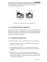
Page 18: ...d the adapter s or the system s For most AT compatibles you will not have to change this jumper To set the jumper place shunts as shown in Figure 2 3 below Figure 2 3 Clock Source Jumper JP 1 When you have completed setting the Clock Source Jumper you are now ready to install the T2015 into your computer 2 4 INSTALLING THE T2015 ADAPTER A T2015 adapter can occupy any 16 bit expansion slot or an XT...

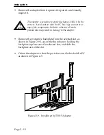
Page 19: ...ckplate in place and slide the backplate out of the slot Figure 2 4 Installing the T2015 Adapter Carefully insert the adapter into the expansion slot as shown in Figure 2 4 Orient the adapter so the PC edge bus connector is pointed down and the ports face out the back of the PC Align the adapter so the PC bus edge connector is lined up with the expansion slot and firmly press the adapter into the ...

Page 20: ...Novell NetWare network operating system The Boot PROM address is linked to the I O address as shown in Table 2 1 on page 2 5 Software installation instructions are included with the Boot PROM 2 5 1 Boot PROM and Socket Alignment To install a Boot PROM remove the Boot PROM from its packaging Insert the Boot PROM into the PROM socket so that the notched corner on the PROM is aligned with the notch o...

Page 21: ...ctivity LED This yellow LED flashes to indicate that the adapter has detected minimum signal strength is active on the Token Ring and is transmitting and receiving data addressed to it 4 Mbit LED This green LED indicates 4 megabit Token Ring speed 16 Mbit LED This yellow LED indicates 16 megabit Token Ring speed Bicolor LED When off this LED indicates that the adapter has not inserted Phantom into...

Page 22: ... The Clock Source Jumper JP1 adjusts the adapter s clock cycle to match the PS 2 model that the adapter is to be installed in Placing a shunt over pins 1 and 2 set the clock source for PS 2 Model 50 compatibility Placing the shunt over pins 2 and 3 adjust the clock source for compatibility with PS 2 Models 70 and 80 To set the jumper locate JP 1 as shown in Figure 2 7 below Figure 2 7 T3015 Clock ...

Page 23: ... after the adapter is installed 2 7 3 Installing the T3015 Adapter To install the adapter in your computer follow these instructions Turn off the power to the PC and peripherals and disconnect all power cords and cables Following the instructions in your computer user manual using static discharge precautions remove the cover from the computer Select the slot in which the adapter will be installed...

Page 24: ...lace over the selected slot and slide the backplate out of the slot Orient the adapter so that the ports face out the back of the PC as shown in Figure 2 9 Figure 2 9 Installing the T3015 Adapter CAUTION The adapter is sensitive to static discharges Hold it by the corners Avoid contact with the PC bus edge connector or any of the components Failure to observe all static precautions may result in d...

Page 25: ... Adapter Description File ADF onto a backup copy of your system s Reference Diskette The ADF is supplied with your Cabletron software The ADF provides Programmable Option Select Parameters for the System Configuration Utility If necessary you can change the parameters during this procedure IMPORTANT Be sure to use a backup copy of the Reference diskette and not the original Reference Diskette when...

Page 26: ... system software drivers are supplied on the Cabletron software diskettes that are shipped with the adapter The drivers are grouped in subdirectories that contain readme files a DOC extension to explain any recent changes in procedure etc The Network Software Installation Guide included with the software contains detailed installation instructions for installing network drivers ...

Page 27: ...apter with a known working adapter The interrupt I O address or memory parameters could be conflicting with another adapter Use a program like Check It to determine what settings are currently in use by other adapters Verify that the cable is attached to the media port that you want to use and that the cable is actually a Token Ring twisted pair cable If a connection to a server or another host ca...

Page 28: ...aining the Cabletron software 2 11 2 Software Tips The following tips may help you avoid software related problems Cabletron supplies different drivers for use with different operating systems Make sure that you are using the correct driver and that the I O hardware switch setting agrees with the software I O setting that you selected If you are using Novell NetWare Cabletron supplies a direct IPX...

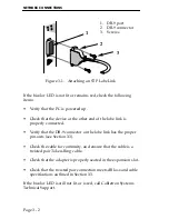
Page 29: ...ts of two twisted pairs One pair RX RX for the incoming receive signal from the upstream neighbor in the Token Ring One pair TX TX for the outgoing transmit signal to the downstream neighbor in the Token Ring The T2015 Token Ring adapter Figure 3 1 is used here for a connection example To connect the adapter to a Token Ring lobe link via the DB 9 port Connect the DB 9 connector 2 Fig 3 1 on the en...

Page 30: ...he DB 9 connector on the lobe link has the proper pin outs see Section 3 3 Check the cable for continuity and ensure that the cable is a twisted pair Token Ring cable Check that the adapter is properly seated in the expansion slot Check that the twisted pair connection meets dB loss and cable specifications outlined in Section 3 3 If the bicolor LED is still not lit or is red call Cabletron System...

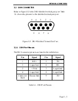
Page 31: ...ts for the shielded twisted pair port Figure 3 2 DB 9 Shielded Twisted Pair Port 3 2 1 DB 9 Port Pinouts The DB 9 connector pinouts are listed in the table below Table 3 1 DB 9 Port Pinouts Pin Signal Pin Signal 1 RX 5 TX 2 Logic Gnd 6 RX 3 5 Vdc 7 Logic Gnd 4 Logic Gnd 8 Logic Gnd Connector Shell Chassis Gnd 9 TX 5 4 3 2 1 9 8 7 6 ...

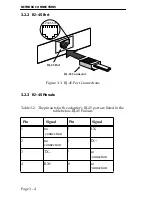
Page 32: ... Connections 3 2 3 RJ 45 Pinouts Table 3 2 The pinouts for the adapter s RJ 45 port are listed in the table below RJ 45 Pinouts Pin Signal Pin Signal 1 no connection 5 RX 2 no connection 6 TX 3 TX 7 no connection 4 RX 8 no connection RJ 45 Port RJ 45 Connector 12345678 ...

Page 33: ...nal to the downstream neighbor in the Token Ring To connect the adapter to a Token Ring lobe link via the RJ 45 port connect the UTP lobe link 4 Fig 3 3 to the adapter by inserting the RJ 45 connector 3 into the RJ 45 port 2 on the adapter Figure 3 4 Attaching a UTP Lobe Link Once the PC is powered up and on the network be sure the bicolor LED 1 is lit The LED will be off when the PC is first powe...

Page 34: ...at the twisted pair connection meets dB loss and cable specifications outlined in Section 3 3 The Token Ring adapter is now ready for operation If you encounter any problems contact Cabletron Systems Technical Support 3 3 NETWORK SPECIFICATIONS This section outlines the Token Ring Network operating and environmental specifications 3 3 1 Cable Specifications Each Token Ring adapter supports IBM shi...

Page 35: ...ype 6 cable is good for up to 66 meters for every 100 meters of Type 1 cable Type 6 cable distance 2 3 x Type 1 cable distance Type 8 One flat STP of 26 AWG stranded wire for under carpet installation Type 8 STP has the same characteristics as Type 9 cabling Type 9 Similar to Type 1 but uses 26 AWG solid wire Due to the higher attenuation Type 9 cable is good for up to 66 meters for every 100 mete...

Page 36: ... in Table 3 2 Since there are two possible ring speeds both frequencies are listed 4 0 MHz and 16 MHz The attenuation values include cables connectors and patch panels Table 1 Cable Type at 4 Mbps at 16 Mbps STP IBM Types 1 and 2 200 meters 656 feet 100 meters 328 feet Voice Grade UTP IBM Type 3 100 meters 328 feet 60 meters 196 feet STP IBM Type 6 only for station to wall plate and patch panels 3...

Page 37: ...externally induced impulses If noise induced errors are suspected it may be necessary to re route cabling away from potential noise sources motors switching equipment high current equipment or to ensure that the electrical wiring in the area is properly wired and grounded WARNING It is the responsibility of the person who sells the system of which the adapter will be a part to ensure that the tota...

Page 38: ...Page 3 10 NETWORK CONNECTIONS ...

Page 39: ...ee Figure 2 3 2 6 setting 2 6 Crosstalk 3 9 D DB 9 connector 3 3 DB 9 port pinouts 3 3 I Impedance 3 9 Installing a Boot PROM 2 8 see Figure 2 5 2 8 Installing the T2015 adapter 2 6 L LANVIEW LEDs 1 3 2 9 16 Mbit LED 2 9 4 Mbit LED 2 9 activity LED 2 9 Bicolor LED 2 9 N Network connections 3 1 connecting to an STP cable 3 1 Network specifications 3 6 Noise 3 9 P Preparing the adapters 2 1 Preparin...

Page 40: ...etting the clock source jumper 2 10 T3015 clock source jumper JP 1 see Figure 2 7 2 10 R Related manuals 1 4 RJ 45 port 3 4 S Safety 3 8 Software 1 3 Software checklist 2 16 diagnostics 2 16 software tips 2 16 Statistics 1 3 T Troubleshooting checklist for adapters 2 15 ...

Reviews: