


Site Requirements
Environment: 32–104
o
F (0-40
o
C) and 5–95% humidity, non-condensing.
An AC power outlet of the appropriate voltage (110–125/60 Hz or 200–240
VAC/50 Hz) must be located within five feet of the device.
For adequate air flow, allow at least four inches of clearance at the rear and at
least two inches at the sides, front, and top. DO NOT remove the rubber
mounting feet from the bottom of the unit, as these provide necessary space for
air flow through the fan. Also, make sure the FRX4000 sits on its mounting
feet, not on its sheet metal bottom surface. Do not place the unit on a surface
that is smaller in area than the spaces between the mounting feet.
If you will be rack mounting the FRX4000, the holes in the vertical mounting
angles in the rack must either be threaded (10-32) or have captive nuts installed.
For reference, an FRX4000 weighs 9 lbs. (4.1 kg), and is 17.5" (44 cm) wide,
11" (27.7 cm) deep, and 1.75" (4.4 cm) high.
Required Equipment
Tools
The only tools you need are a small flat-head screwdriver and a medium
Phillips-head screwdriver.
User Cables
The LAN interface on the Ethernet model of FRX4000 is provided in RJ-45
(UTP) and 15-pin "D" female (AUI, for Thicknet). The LAN interface on the
Token Ring model is provided in RJ-45 (UTP) and 9-pin "D" female (STP).
The LAN cable and, if Ethernet AUI, the transceiver, must be provided by the
customer.
The optional CSU/DSU interface is RJ-48S. The cable must be provided by the
customer.
Assuming that you ordered the necessary WAN interface cables with the
FRX4000, you will need to know which cable will plug into which WAN port.
Table 1 (on page 7) lists the WAN ports and cables.
Installation & Setup Guide
1
Operator Interface
The FRX4000 does not require a keyboard or terminal for normal operation.
However, setup and configuration of a new FRX4000 requires a directly con-
nected async terminal or a PC emulating a terminal.
Set the async terminal device for:
9600 bps
Autowrap
Application keypad
8 bits no parity
No newline
Application cursor key
No break
VT100 mode
Tab every 8 columns
For direct connection to a terminal or PC, each FRX4000 is shipped with:
•
Cable, DB9S to DB9S, 5 feet, Cabletron number FRX-PC-CAB, for
connecting the Console port (see Figure 7 on page 6) directly to a PC
(with software emulating an async terminal). (See Figure 1.)
•
Adapter, DB9P to DB25S, Cabletron number FRX-9/25-ADAP, for
connecting the FRX4000 directly (via cable FRX-PC-CAB) to a cus-
tomer-supplied async terminal (See Figure 2).
•
Cable, DB9S to DB9P, 5 feet, Cabletron number FRX-MOD-CAB, for
connecting the FRX4000 to a modem. (See Figure 3.) This requires the
following, supplied by the customer:
• Two auto-answer modems, capable of 9600 bps. (If the modem at
the FRX4000 end does not have a DB25S connector, you will also
need a gender adapter.)
• One straight-through cable from async terminal to modem.
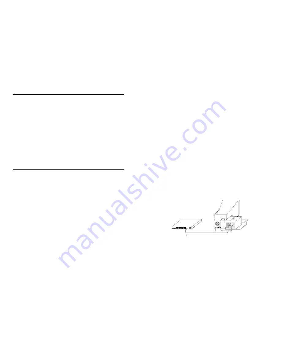
Figure 1 Auxiliary Console Cabling - Console Port to PC
2
FRX4000
PC Monitor
FRX4000
PC-to-Console port cable
(FRX-PC-CAB)


