


LANVIEW LEDs
4-2
The functions of the two System Status LEDs, System Management Bus (SMB)
and the CPU, are listed in Table 4-1.
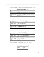
The function of the FNB Receive LED is listed in Table 4-2.
The function of the FNB Transmit LED is listed in Table 4-3.
Table 4-1. System Status LEDs (SMB and CPU)
LED Color
State
Description
Green
Functional
Fully operational.
Yellow (Flashing)
Crippled
Not fully operational (i.e., one bad port).
Yellow/Green
Booting
Blinks yellow and green while booting.
Red
Reset
Normal power-up reset.
Red (Flashing)
Failed
Fatal error has occurred.
Off
Power off
Module powered off.
Table 4-2. FNB Receive LED
LED Color
State
Red
Fault or Error
Green
Link, No activity, Port enabled
Yellow (Flashing)
Activity (Flashing rate indicates rate of activity).
Off
No activity
Table 4-3. FNB Transmit LED
LED Color
State
Red
Fault or Error
Yellow (Flashing)
Port in standby state
Green (Flashing)
Activity (Flashing rate indicates rate of activity).
Off
No activity
Summary of Contents for MMAC-Plus 9T125-24
Page 1: ...9032053 01 SmartSwitch 9000 9T125 24 User s Guide...
Page 2: ......
Page 6: ...Notice iv...
Page 8: ...Contents vi...
Page 24: ...Operation 3 6...
Page 28: ...LANVIEW LEDs 4 4...


