background image

~ 11 ~

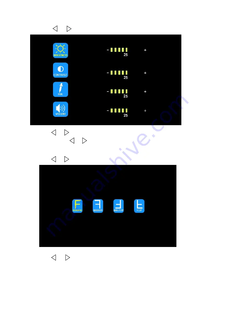
(2) Press

or

to select PICTURE, press OK to enter

.

Press

or

to select BRIGHTNESS / CONTRAST / HUE / VOLUME, press OK

to enter. Press

or

to adjust. Press OK to exit. Press MENU return to main

menu.

(3) Press

or

to select MIR-FLIP, press OK to select

.

Press

or

to select NORMAL / MIRROR / MIR-FLIP / FLIP. Press MENU

return to main menu.

Summary of Contents for A-CDW7M1C

Page 1: ...Operating Instructions 2 4G Digital 7 Wireless Color LCD Monitor Please read this manual thoroughly before operating the device keep it for future reference V 1 1 ...

Page 2: ... you are solely responsible for the appropriate operation of your vehicle and the safety of your passengers and pedestrians and you should abide all state and local traffic laws and regulations Do not over use any features of this system that it might distract you from safe driving The top priority of your driving should always be the safe operation of your vehicle A I Products Inc will not accept...

Page 3: ...onitor is not designed to be waterproof Operating Precautions 1 The device may be powered by a 12 or 24 volt automotive battery or vehicle electrical system 2 Make sure all cables are connected properly Observe polarity Improper cable connections may damage the monitor Remove the power cable connections when you do not intend to use the device Warning 1 High voltage is present within the monitor T...

Page 4: ...ing instructions in the literature accompanying the appliance This symbol is intended to alert the user not to waste electrical and electronic equipment CAUTION You are cautioned that any changes or modifications not expressly approved in this manual could void your warrantee and necessitate expensive repairs Declaration of conformity This device complies with Part 15 of the FCC Rules Operation is...

Page 5: ...ard speaker 12 Auto switch to the working channel when trigger is activated 3 Technical Specifications LCD size 7 Resolution 800 x 3 RGB x 480 Contrast 500 1 Brightness 400 cd m Viewing Angle U 50 D 70 R L 70 Dot pitch 0 0642 W x 0 1790 H Aspect Ratio 16 9 Channel 4 channels Operating Frequency 2400 2483 5 MHz Receiving Sensitivity 89 dBm Decompression Form MPEG4 Modulation 2 4G FSK GFSK Time Dela...

Page 6: ... 4 4 Accessories Special Notice Accessory supply may be different for different application U Support Bracket Center Mount Bracket Sun Shield Power cable IR Remote control Angle Adjustment Screws ...

Page 7: ...save user settings Press OK button shortcut for start stop recording Press OK button for 3 seconds shortcut for PAIRING Loudspeaker Menu Digital Color LCD screen Power indicator Remote control sensor Light level Mounting bracket installation Volume decrease Select channels Micro SD TF Card Slot ...

Page 8: ...for start stop recording Volume decrease and menu selection left decrease and menu selection Jump key selector Fast jump to the display mode specified by SYSTEM Press to turn on off the monitor Press to show menu or exit menu Volume increase and menu selection right MIR Flip selection Fast pairing when camera is activated PAL NTSC TV system selector ...

Page 9: ...Press OK button shortcut for start stop recording MENU Press to display menu or exit menu VOL Volume decrease and menu selection left VOL Volume increase and menu selection right SEL Jump key selector Fast jump to the display mode specified by SYSTEM SETUP JUMP KEY PAIR Fast pairing when camera is activated SYS PAL NTSC TV system selector MIR MIR Flip selection ...

Page 10: ...ting bracket 7 2 Installation of U support Bracket Support attaching piece Knob Red wire to positive power supply of DC 10 32V Black wire to Ground Brown wire to positive power wire of reversing light White wire to positive power wire of left light Blue wire to positive power wire of right light Green or yellow wire to other positive power wire Battery Video inputs Camera DC 12V Automobile applica...

Page 11: ... is activated 7 3 4 When the brown wire is connected to the positive wire of reversing light the monitor automatically switches to CAM4 back up camera when the reversing light is activated The distance label will be displayed 7 3 5 When the yellow wire is connected to the positive wire the monitor automatically switches to quad or split display Connection may vary due to different applications 7 4...

Page 12: ...MODE 2 PICTURE 3 MIR FLIP 4 RECORD 5 AUTOSCAN 6 SYSTEM 7 PLAY 8 PAIRING 1 Press or to select MODE Press OK to enter Press or to select SPLIT QUAD mode Select OFF to exit SPLIT QUAD mode Press MENU to return to main menu Note When select OFF to exit split quad mode split quad trigger display is disabled Monitor will switch to single image mode ...

Page 13: ...s or to select BRIGHTNESS CONTRAST HUE VOLUME press OK to enter Press or to adjust Press OK to exit Press MENU return to main menu 3 Press or to select MIR FLIP press OK to select Press or to select NORMAL MIRROR MIR FLIP FLIP Press MENU return to main menu ...

Page 14: ...ns yellow press or to select ON or OFF Press OK to exit Press MENU return to main menu OVERWRITE Previous video file will be overwritten when disk is full FORMAT Micro SD card must be formatted before being used All files in Micro SD card will be lost once disk is formatted 5 Press or to select AUTOSCAN Press OK to enter ...

Page 15: ... select TIME Press OK to set Press or to adjust Press OK to continue setting COLOR SYS Press or to select COLOR SYS Press OK to enter Press or to select NTSC PAL AUTO DIM Press or to select AUTO DIM Press OK to enter press or to select ON OFF When set as ON backlighting automatically adjusts in accordance with the outer brightness ELETRONIC DISTANCE LABEL Press or to select ELETRONIC DISTANCE LABE...

Page 16: ...s named in format of YYMMDD 130903 means the folder is created on Sep3rd 2013 Video files can be searched under daily folder It is named in format of HHMMSS_ Channel Source 100953_3 means the file is created for camera 3 at 10 09 53 am All video files are in AVI format with maximum recording time is 10 minutes for each file ...

Page 17: ... 5s 4 If auto pairing is completed the video will be displayed If it is failed a message No Signal will be displayed Repeat the pairing procedure Manual pairing 1 Choose the channel that needs to be set up the monitor will display the message PAIRING START 50 2 Within the countdown of 50 seconds power on the camera Press the pairing button on the camera 3 The monitor and cameras will synchronize t...

Page 18: ...roubleshooting The symptoms described below do not necessarily mean a failure within the display Please check the following items before you initiate request for repair Symptoms Possible Causes Solutions No picture Improper connection of automobile adapter Use of improper power supply Power switch is set OFF No signal Check whether the camera has power supply Pair the monitor and the camera again ...

Page 19: ...ertical Sync Frequency 50 Hz 60 Hz Video Output 1 0Vp p 75Ohm Gamma Consumption 0 45 AGC Auto S N Ratio Better than 46 5dB White Balance Auto Electronic Shutter 1 60 NTSC 1 50 PAL 1 100 000 Seconds BLC Auto Storage Temperature 40 80 RH95 MAX Operating Temperature 30 70 RH95 MAX Power Supply DC12V Waterproof rating IP69K Viewing Angle 120 Audio Yes Minimum Illumination 0 Lux Night vision distance 1...

Reviews: