background image

Optimal positioning for a 2.0 or stereo system 

(page 6)

 For the ideal positioning of your speakers follow diagram A. If 

«d» is the distance between the two speakers, this distance must 
be higher than 5 ft (1.5 m) and the two speakers must be at equal 
distance from the listening area which forms with them an equi-
lateral triangle. 

 The drivers must be directed towards the listening area. 
 The speakers should be located so that their diffusion follows 

the longest dimension of the room. 

 Generally speaking it is better to avoid putting the speakers in 

the corners of a room as this amplifies the low frequencies and 
tends to enhance the room resonances. If possible it is better to 
place the speakers at least 8 inches (20 cm) from the walls.

 To ensure a sufficient ventilation of the electronic components 

of the active loudspeakers, always leave 10 cm or more free space 
between the rear of the cabinet and any wall, mobile partition, 
piece of furniture, curtain or cloth. 

 No solid object or piece of furniture should be placed between 

the speakers and the listener. An effect of such a mask, even par-
tial, disturbs completely the sound reproduction as it attenuates 
the high frequencies and also, in most cases, the midrange fre-
quencies.

 Placing these active loudspeakers in niches is  prohibited. It 

alters the frequency response of the speaker and prevents proper 
ventilation of the electronics.

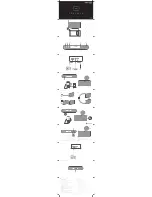
SPEAKER-DAP PREAMPLIFIER CONNECTION 

(page 4)

Connect both optical cables (the ones delivered with the system or 
equivalent models with the required lengths) to the 

b2

  «Speaker 

OUT» terminals of the DAP and to the 

a2

 «OPT In»  sockets of the 

loudspeakers.

a3

 ASSIGN switch settings: select Right for the loudspeaker at your 

right when facing the speakers and Left for the speaker on the left..
Check on both loudspeakers that the  

a4

 switch is pressed «on» to 

activate the illumination of the logos in front of the cabinet when 
the system is in use.

UNPACKING (page 2 & 3)

The system is delivered in 3 packages:

 2 x crates for the active loudspeakers
 1 x cardboard box for the DAP (Digital Adaptive Preamplifier), 

the remote control, 2 AAA batteries, 6 cones, 1 hex key for the 
release of the castors, 1 rod for the adjustment of the cones, 2 
class I power cables, 1 class II power cable, two 10 m optical 
cables, 1 measurement microphone and base, 1 owner’s manual, 
1 warranty card, 1 pair of gloves and a micro-fiber cloth. 

Speakers unpacking:

 follow carefully the steps detailed on 

pages 2 and 3, then assemble the parts of each empty packing 
including all the packing accessories and store the crates in a dry 
place for future use.

Cardboard box unpacking:

 after removing the top carton 

flaps, fold them right back and remove the accessories and the 
foam sheet to reach the preamplifier packing. Check  that none 
of  the above listed accessories are missing.
The packing must be retained at least during the validity period 
of the warranty. 

POSITIONING 
Speakers positioning 

The L’Océan loudspeakers are delivered with a set of decoupling 
cones (page 4). These accessories are to be screwed in the inserts 
on the base of the speakers, after having removed the castors with 
the help of the hex key. Adjust the height of the cones by using 
the rod also delivered with the speakers. These accessories ensure 
the stability of the speaker while limiting resonance coming from 
certain types of flooring such as wooden floors.

Speakers are delivered with a front grille to protect drivers. It is 
possible to use them without this front grille, by gently pulling its 
top end in order to cut off its magnetic link with the magnets to 
the front panel. To get the grill back in place, position it in front 
of the speaker and approach it to the front panel until the ma-
gnetic link is effective. These operations must be carried out very 
smoothly in order not to damage the veneer covering the magnets 
on the front panel of the speaker .
Powerful drivers generate magnetic fields that can extend beyond 
the boundaries of the speaker cabinet. We recommend you keep 
magnetically sensitive articles (CRT TVs and computer monitors, 
computer discs, audio and video tapes, swipe cards...) at least 
1.5 ft (50 cm) away from the speaker.

Positioning speakers in a room

In addition to the vertical position of the speakers themselves, 
their location in the listening room, as well as the acoustical cha-
racteristics of the room, are also very important. As it is impos-
sible to indicate a typical location of speaker systems without a 
few tests, we suggest several general rules that are important to 
apply in order to obtain the best listening results.

L’OCÉAN SYSTEM

These speakers are very heavy, so 2 persons minimum are requi-
red to unpack and re-pack them.

ATTENTION :


the L’Océan loudspeakers must be used 

with either the cones or the castors to ensure the right air cooling 
for the built-in electronics. Any use without it will invalid any 
warranty claim.

ATTENTION :


Before operating the unit,be sure that the 

operating voltage of your unit is identical with that indicated 
on packing, the warranty card or the sticker on the base of the 
speaker. If not, please follow the instructions of the POWER 
SUPPLY section.

ATTENTION :


To prevent any alteration of the signal 

transmission through the optical cables, never roll up the cable 
tightly. The diameter of the loops must be at least ten times bigger 
than the thickness of the cable itself. Keep the ends of the bare 
optical cable very clean. If necessary, clean them with isopropyl 
alcohol.

CAB ocean-v6.indd   19

10/10/11   11:29

Summary of Contents for L'OCEAN

Page 1: ...www cabasse com notice d installation du systeme owner s manual for the system betriebsanleitung des systems L OCƒAN CAB ocean v6 indd 1 10 10 11 11 29 ...

Page 2: ...à ne pas toucher le haut parleur TC23 Remove together the front grill and its foam protection ATTENTION do not hit the TC23 driver when operating Ziehen Sie den Grill zusammen mit seinem Schaumformteil heraus VORSICHT Berühren Sie beim Herausziehen die Membranen nicht Couper les 4 bandes de cerclage Unstrap the crate Zerschneiden Sie die vier Packbänder Retirer le couvercle Remove the top board En...

Page 3: ...ve the foam shield Ziehen Sie das Schaumformteil heraus Enlever la mousse de protection Remove the foam shield Ziehen Sie das Schaumformteil heraus ATTENTION 2 personnes sont nécessaires pour effectuer le déballage L enceinte est protégée par une housse en tissu microfibre Garder un jeu de bloc de mousse disponible pour le remplacement des roulettes par les cone vérins une fois les enceintes proch...

Page 4: ...VERINS REPLACEMENT OF THE DELIVERY CASTORS BY THE CONES ABNEHMEN DER TRANSPORTROLLEN UND ANSCHRAUBEN DER KEGELFÜSSE ASSIGN Left Right A4 A2 A3 A1 A5 ASSIGN Left Right ASSIGN Left Right B1 1 B7 B1 0 B1 2 B8 B4 B2 B1 B6 B5 B9 ASSIGN Left Right A4 A2 A3 A1 A5 CAB ocean v6 indd 4 10 10 11 11 29 ...

Page 5: ...CHTS ABWÄRTS 5 SCROLL LEFT UP DEFILEMENT GAUCHE HAUT LINKS AUFWÄRTS 6 VOLUME CONTROL REGLAGE DU VOLUME LAUTSTÄRKEREGLER 7 MUTE ON MUTE OFF COUPURE RESTAURATION DU SON STUMMSCHALTUNG MUTE 8 DAP DISPLAY SETTING REGLAGE DE LA LUMINOSITE DE L ECRAN DU DAP DIMM FUNKTION DISPLAY 9 HEADPHONE SOCKET PRISE CASQUE KOPFHÖRERANSCHLUSS DISPLAY VOLUME MUTE 5 6 9 7 4 ASSIGN Left Right 1 2a 3 DISPLAY VOLUME MUTE ...

Page 6: ...auchbar No No No No Yes Yes Yes Yes Zone d écoute Listening area Hörplatz Positions recommandées du microphone Recommended positions for the microphone Richtige Mikrofonposition Positions du microphone déconseillées Microphone positions to be avoided Falsche Mikrofonposition No No No No No No No No No No No No No No No Yes Yes Yes Yes Yes Yes Yes Yes Yes Yes Yes B RECOMMANDATIONS POUR LES POSITION...

Page 7: ...tion des câbles d alimentation Le cheminement des câbles d alimentation doit être prévu de telle sorte qu ils ne puissent pas être piétinés pincés coincés par d autres appa reils posés dessus et une attention toute particulière doit être accordée à l adéquation des prises et à la liaison du cordon avec l appareil Foudre Pour une meilleure protection de l appareil pendant les orages ou s il doit re...

Page 8: ...près de cette prise DEBALLAGE DU SYSTEME pages 2 et 3 Le système L Océan est livré dans 3 emballages 2 x caisses bois contenant les enceintes 1 x carton contenant le préamplificateur DAP Digital Adaptive Preamplifier Préamplificateur Numérique avec Adaptation au local sa télécommande 2 piles AAA 6 cônes vérin une clé hexagonale pour le démontage des roulettes une tige pour l ajustement en hauteur ...

Page 9: ...mentation du préamplificateur DAP La prise B1 sert à alimenter le processeur L alimentation s adapte automatiquement à tout voltage de 100 à 240 V UTILISATION DES COMMANDES EN FAÇADE DU DAP ET SUR LA TELECOMMANDE Toutes les fonctions du système L Océan sont accessibles par les commandes en façade du préamplificateur DAP et sur la télécom mande exceptées les commandes marche arrêt 2A veille 2B et a...

Page 10: ...mmande 2 Presser le bouton SELECT figure de Lissajou sur la télécom mande pour confirmer le lancement du protocole de mesures 3 Connecter le microphone livré avec le DAP dans la prise jack Set Up mic B1 2 au dos du préamplificateur 4 Mesurer la distance séparant les tweeters de chaque en ceinte sélectionner la bonne valeur en faisant tourner le bouton SELECT puis valider en poussant le même bouton...

Page 11: ...e puis valider Conti nue pour passer à l étape suivante 14 Placer le microphone en position P3 à la 3ème positon d écoute Si la position d écoute est unique placer le micro phone légérement à gauche 30 cm au dessous et 60 cm derrière P1 Confirmer la mesure puis valider Continue pour passer à l étape suivante 15 Placer le microphone en position P4 proche du mur arrière à une hauteur représentant le...

Page 12: ...outon SE LECT pour sortir du menu CRCS Débrancher le microphone Le système CRCS est opérationel 1 Sélectionner PRESET préréglages dans le menu obtenu après avoir appuyé sur le bouton FUNCTION fonction du DAP ou de la télécommande Valider sélectionner CRCS puis valider 2 Choisir off et valider 3 Suivre la procédure analogue pour réactiver le CRCS avec les paramètres en mémoire PRESET CRCS On 1 Pour...

Page 13: ...uche FUNCTION 2 Choisir l option désirée la position par défaut est dB soit l extinction complète du signal Les 2 autres options dimi nuent le volume sonore au moment de l activation du mute soit de 20 dB soit de 50 dB 3 La fonction Mute s active en pressant le bouton Mute du DAP ou de la télécommande Mute s affiche alors sur l écran du DAP 4 Une seconde pression sur le bouton Mute désactive la fo...

Page 14: ...our revenir aux noms par défaut de toutes les sources choi sir Default et valider 1 Il est possible d utiliser le DAP comme un processeur connec té à un préamplificateur stéréo ou multicanal La fonction Straight permet de shunter le contrôle de volume L activa tion et désactivation du CRCS et corrections graves aigus sont opérationnelles Dans le cas d une liaison symétrique avec un préamplificateu...

Page 15: ...sures avec moins de bruit Une incohérence a été relevée lors du calcul quant à la position du microphone vérifier et confirmer la distance entre les enceintes cf page 10 pt 4 du MISE EN SERVICE DU CRCS enlever tout objet ou personne pouvant faire écran entre le microphone et les tweeters des enceintes recommencer la séquence avec cette valeur de distance Recommencer la séquence CRCS depuis de débu...

Page 16: ...s tous les jours des lettres de clients satisfaits du choix de leurs enceintes et ces lettres sont pour nous la plus belle récompense de nos efforts MARQUAGE DEEE Traitement des appareils électriques et électro niques en fin de vie applicable dans les pays de l Union européenne Ce symbole représentant une poubelle sur roues barrée d une croix apposé sur chaque produit à l arrière du DAP et des enc...

Page 17: ...5VAC Température d utilisation 10 C à 30 C Température de stockage 0 C à 60 C Taux d humidité en utilisation 20 à 85 SPECIFICATIONS PREAMPLIFICATEUR DAP Alimentation 100 240 VAC 50 60 Hz Consommation nominale 25W 230V 25W 115V Consommation mode veille 0 35W 230VAC 0 15W 115VAC Consommation mode arrêt 0 0W 230VAC 0 0W 115VAC Température d utilisation 10 C à 30 C Température de stockage 0 C à 60 C T...

Page 18: ... are not sure of the type of power available please contact your reseller or the local power company Power cords The power cords must be laid out in such a way that they cannot be walked on pinched bent under other devices Also pay special attention to the matching of the plugs and the connection of the cord to the device Lightning For better protection against lightning or if the device must rema...

Page 19: ...on flaps fold them right back and remove the accessories and the foam sheet to reach the preamplifier packing Check that none of the above listed accessories are missing The packing must be retained at least during the validity period of the warranty POSITIONING Speakers positioning The L Océan loudspeakers are delivered with a set of decoupling cones page 4 These accessories are to be screwed in ...

Page 20: ...ase contact your dealer for modification Each L Océan loudspeaker must be connected to a grounded power socket able to deliver 12 A 2 Power supply of the Digital Adaptive Preampli fier DAP The socket B1 is used to power the DAP The built in power trans former is designed to run with any voltage from 100 to 240 V USE OF THE DAP FRONT PANEL BUTTONS AND OF THE REMOTE CONTROL KEYS All the functions of...

Page 21: ... the FUNCTION button 1 on either the DAP or the remote control and then select CRCS 2 Press SELECT or to confirm the launch of the measure ments procedure 3 Connect the measurement microphone in the Set Up mic socket B1 2 located in the back plate of the DAP 4 Enter the measured distance between the tweeters of both loudspeakers with the SELECT 4 5 knob and validate with 1 5 Start of the measureme...

Page 22: ...ate the launch of the measurement session and validate Continue when OK for next step 14 Place the microphone on P3 if there is no 3rd listening place position the microphone between P1 and P3 Validate the launch of the measurement session and validate Continue when OK for next step 15 Microphone on P4 close to the rear wall at a height equal ling 2 3 of the floor ceiling distance e g at 1 70 m fr...

Page 23: ...lose the CRCS menu Unplug and store the microphone You are ready for music 1 Select FUNCTION PRESET CRCS and validate off with 1 2 Select off and validate 3 To get the CRCS corrections back select FUNCTION PRESET CRCS and validate on with 1 1 Once the CRCS module is active it s possible to access di rectly to the Spectrum Adjustment and skip the measurement phases Select FUNCTION followed by PRESE...

Page 24: ...ttings are stored and will be effective again when the Direct is set back on off 1 Press FUNCTION 3 and select User Mute 2 Choose your option the dB default setting turns off the sound when 50 dB and 20 dB attenuate the volume by the specified value 3 Press the Mute 7 button of the DAP or the remote to attenuate the sound Mute is displayed on the bottom right of the DAP screen 4 Press mute again t...

Page 25: ...he initial factory names of all the sources select Default and confirm 1 The DAP can be used as a slave of another stereo of mul ti channel preamplifier thanks to the Straight mode This mode cancels the volume controls of the DAP but keeps the CRCS and tone corrections available For a balanced connec tion to a preamplifier with a high level output use the XLR2 terminals B1 1 of the DAP and press d...

Page 26: ...uter notices an incoherency betwen the measurements and the microphone positions control the distance between the twee ters of the loudspeakers and confirm the value entered at the start of the CRCS protocole cf pt4 of CABASSE ROOM COMPENSATION SYSTEM CRCS SETUP on page 21 remove anything between the tweeters and the microphone start the CRCS session again Start the CRCS session from the beginning...

Page 27: ...amplification of the loudspeakers WEEE MARK Disposal of Wastes of Electrical Electronic Equipment Applicable in the European Union This symbol on the product consisting of the crossed out wheelie bin and placed on each product on the back plates of the DAP and the loudspeakers and on the inner side of the lid of the remote control indicates that this product shall not be treated as house hold wast...

Page 28: ...temperature range 10 C to 30 C Storage temperature 0 C to 60 C Useable humidity range 20 to 85 L OCÉAN LOUDSPEAKER ELECTRONICS SPECIFICATIONS DAP PREAMPLIFIER SPECIFICATIONS Voltage 100 240 VAC 50 60 Hz Power consumption 25W 230V 25W 115V Standby power consumption 0 35W 230VAC 0 15W 115VAC Power consumption when off 0 0 W 230VAC 0 0 W 115VAC Useable temperature range 10 C to 30 C Storage temperatu...

Page 29: ...ren kann Netzanschluss Das Gerät darf nur mit dem Stromnetz ver bunden werden wenn die Netzspannung der Steckdose an der das Gerät betrieben werden soll der Betriebsspannung entspricht welche in der dem Gerät beiliegenden Betriebsan leitung und auf den am Gerät angebrachten Hinweisen vor geschrieben ist Wenn Sie sich nicht sicher sind welche Ver sorgungsspannung bei Ihnen verfügbar ist wenden Sie ...

Page 30: ...ung zu nehmen Über prüfen Sie bitte die Vollständigkeit des Zubehörs anhand oben ste hender Liste Wir empfehlen Ihnen die Originalverpackung für Lautsprecher und Steuergerät zumindest für den Garantiezeitraum aufzubewahren um jederzeit einen sicheren Transport zu gewährleisten AUFSTELLEN DER LAUTSPRECHER Die Lautsprecher werden mit sechs Kexgelfüßen geliefert Die Kegel entkoppeln den Lautsprecher ...

Page 31: ...ler Die Lautsprecher dürfen nur an Steckdosen betrieben werden welche einen Schutzerdung und eine Stromlieferfähigkeit von mindestens 12A pro Steckdose aufweisen Verbinden Sie die Stecker der mitgelieferten Netzkabel mit den Netz buchsen A1 in den Anschlussfeldern der Lautsprecher Verbinden Sie anschließend die Netzkabel mit dem Stromnetz b Netzanschluss DAP Steuergerät Ein integrierter Umformer e...

Page 32: ...er beiden Drehschalter 4 5 den Menüpunkt CRCS an 2 Der Einmessvorgang wird mit 1 SELECT oder gestartet 3 Verbinden Sie das beiliegende Messmikrofon an der mit Set Up mic bezeichneten Buchse B1 2 im Anschlussfeld des Steuer gerätes 4 Geben Sie unter Zuhilfenahme einer der beiden Drehschalter 4 5 den Abstand der Hochtoneinheiten beider Lautsprecher zueinender ein Bestätigen Sie die Eingabe mit 1 5 P...

Page 33: ...egeben 12 Ist die Messung korrekt erfolgt bestätigen Sie diese mit 1 13 Die Messposition P2 erfast einen zweiten Hörplatz zum Mu sikhören Gibt es keine Position für eine zweiten Hörplatz wird das Mikrofon ca 1 Meter rechts 30cm über und 30cm hinter der Messposition P1 aufgestellt Starten und speichern Sie die Messung mit 1 14 Die Messposition P3 erfasst einen weiteren dritten Hörplatz zum Musikhör...

Page 34: ... in allen Display Anzeigen sichtbar 27 Wählen Sie mit 4 5 den Menüpunkt Back aus Bestäti gen Sie mit 1 um das Menü CRCS zu schließen 1 Rufen Sie mit 3 FUNCTION das Setup Menü auf wählen Sie mit einem der beiden Drehschalter 4 5 das Untermenü Preset und dann den Menüpunkt CRCS aus Bestätigen Sie nach Anwählen von Off mit 1 SELECT oder 1 2 Die Deaktivierung des CRCS System wird im Display bestätigt ...

Page 35: ... die Menüpunkte User und Mute an 2 Es könne drei Einstellungen programmiert werden 0dB schaltet das Gerät komplett stumm 20dB und 50dB ver ringern den Pegel um den entsprechenden Wert Bestätigen Sie die gewünschte Einstellung nach dem Anwählen mit 1 3 Drücken von 7 MUTE am Gerät oder auf der Fernbedie nung senkt die Lautstärke auf den programmierten Pegel ab Im Display wird rechts unten Mute angez...

Page 36: ...ngang angewählt werden Nach Anwahl des Eingangs stellt Cancel und 1 den vorherigen Namen des Eingangs wieder her 2 Aufrufen der werksseitig programmierten Eingangs Bezeich nung Gehen Sie wie oben beschrieben vor Nach Anwahl des Eingangs stellt Default und 1 die in der Werkseinstellung programmierte Bezeichnung des Eingangs wieder her 1 Mittels einer Direkt Betriebsart kann der DAP zusammen mit ein...

Page 37: ...en Sie den Einmessvorgang erneut durch Fehler Das gewünschte Quellgerät wird vom DAP nicht erkannt nicht im Display angezeigt Rechter und linker Kanal sind vertauscht Kein korrekte Stereo Abbildung Fehlermeldung Insert Microphone wird angezeigt Fehlermeldung To much noise wird angezeigt Fehlermeldung Measurement error Cancel wird während des Einmessens der Messpunkte P1 bis P5 angezeigt Fehlermeld...

Page 38: ...rechersystems Rückseite des Steuergerätes und der Lautsprecher sowie an der Innenseite des Batteriefachdeckels der Fernbedienung der Verpackung und oder den Begleitdokumenten weist darauf hin dass gebrauchte elektrische und elektronische Produkte nicht über den Haushaltsmüll entsorgt werden dürfen Zur richtigen Handhabung Rückgewinnung und Wiederverwer tung von Altprodukten bringen Sie diese bitte...

Page 39: ...0V 0W bei 115V Umgebungstemperatur ausgeschaltet 0 bis 60 Grad Umgebungstemperatur im Betrieb 10 bis 30 Grad Umgebungsluftfeuchtigkeit im Betrieb 20 bis 85 DATEN DER L OCÉAN LAUTSPRECHER ELEKTRONIK DAP STEUERGERÄT DATEN Netzanschluss Wechselstrom 100 240 VAC 50 60 Hz Stromverbrauch 25W 230V 25W 115V Stromverbrauch im Stand By 0 35W 230VAC 0 15W 115VAC Stromverbrauch ausgeschaltet 0 0W 230VAC 0 0W ...

Page 40: ...Cabasse SA 210 rue René Descartes BP 10 29280 Plouzané Tel 33 0 2 98 05 88 88 Fax 33 0 2 98 05 88 99 www cabasse com NOT0291 1109 CAB ocean v6 indd 40 10 10 11 11 29 ...

Reviews: