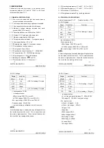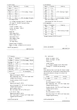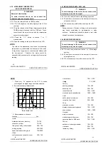
4.13 MEASURING DUTY
4.13.1 Plug the black test lead into the COM jack and the
red test lead into the Hz jack.
4.13.2 Set the rotary selector to the Hz range position.
4.13.3 Press the "Hz/DUTY" button to switch to DUTY
measurement (or press the “Hz/DUTY” button at the
AC/DC V range to switch to DUTY measurement).
4.13.4 Connect test leads to the two end of the source or
load for measurement.
4.13.5 Take the reading on the main display of the LCD.
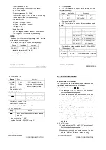
4.14 MEASURING DC CURRENT
WARNING
Beware of Electrocution.
Turn off the power of the circuit to be measured
before connecting the meter to the circuit.
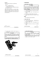
4.14.1 Plug the black test lead into the COM jack. When
the current to be measured is under 400mA, plug the
red test lead into the mA jack; when the current to be
measured is over 400mA but under 10A, plug the red
test lead into the 10A jack.
4.14.2 Set the rotary selector to the
A range position.
4.14.3 Press the "SELECT" button to switch to DC
measurement. Then press the “RANGE” button to
choose the auto range or manual range mode.
- 32 -
DIGITAL MULTIMETER
OPERATING
INSTRUCTION
4.14.4 Connect the test leads to the circuit for measurement.
4.14.5 Take the reading on the main indicator of the LCD.
The polarity symbol denotes the polarity of the end
connected by the red test lead.
NOTE:
1) At the manual range mode, when only ‘OL’ or ‘-OL’ is
shown on the LCD, it means the measurement has
exceeded the range. A higher range should be
selected.
2) At the manual range mode, when the scale of the value
to be measured is unknown beforehand, set the range
to the highest.
3) “
” means the maximum current of the mA jack is
400mA and the maximum current of the 10A jack is
10A. At the 10A jack, current exceeding the limit will
blow the fuse.
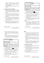
4.15 MEASURING AC CURRENT
WARNING
Beware of Electrocution.
Turn off the power of the circuit to be measured
before connecting the meter to the circuit.
4.15.1 Plug the black test lead into the COM jack. When the
current to be measured is under 400mA, plug the red
test lead into the mA jack; when the current to be
measured is over 400mA but under 10A, plug the red
- 33 -
DIGITAL MULTIMETER
OPERATING
INSTRUCTION
test lead into the 10A jack.
4.15.2 Set the rotary selector to the
A range position.
4.15.3 Press the "SELECT" button to switch to AC
measurement. Then press the “RANGE” button to
choose the auto range or manual range mode.
4.15.4 Connect the test leads to the circuit for measurement.
4.15.5 Take the reading on the main indicator of the LCD.
NOTE:
1)) t the manual range mode, when only ‘OL’ or ‘-OL’ is
shown on the LCD, it means the measurement has
exceeded the range. A higher range should be
selected.
2) Under the manual range mode, when the scale of the
value to be measured is unknown beforehand, set the
range to the highest.
3)
” means the maximum current of the mA jack is
400mA and the maximum current of the 10A jack is
10A. At the 10A jack, current exceeding the limit will
blow the fuse.
- 34 -
DIGITAL MULTIMETER
OPERAT
INSTRUCTION
ING
4.16 MEASURING RESISTANCE
WARNING
Beware of Electrocution.
When measuring in-circuit resistance, make sure
that the power of the circuit under test has been
turned off and that all capacitors have been fully
discharged.
4.16.1 Plug the black test lead into the COM jack and the
red test lead into the
Ω
jack.
4.16.2 Set the rotary selector to the
Ω
range position.
4.16.3 Press the "SELECT" button to switch to
Ω
measurement. Then press the “RANGE” button to
choose the auto range or manual range mode.
4.16.4 Connect the test leads to the ends of the resistor or
circuit for measurement.
4.16.5 Take the reading on the main indicator of the LCD.
NOTE:
1)) t the manual range mode, when only ‘OL’ or ‘-OL’ is
shown on the LCD, it means the measurement has
exceeded the range. A higher range should be
selected.
2) When the input is open, ‘OL’ will appear on the LCD to
indicate that the range has been exceeded.
3) For measuring resistance above 1M
Ω
, it may take a
few seconds to get a steady reading. This is normal
for high resistance reading.
- 35 -
DIGITAL MULTIMETER
OPERAT
INSTRUCTION
ING


