background image

24

24

3 Adjustments

3.3 

Adjusting the Belt Tension at the Main Drive Motor

Danger!

Risk of death via electric shock!


Before opening the housing cover, disconnect the device from the mains supply and wait at least one 
minute until the power supply unit has discharged.

1

1

1

2

3

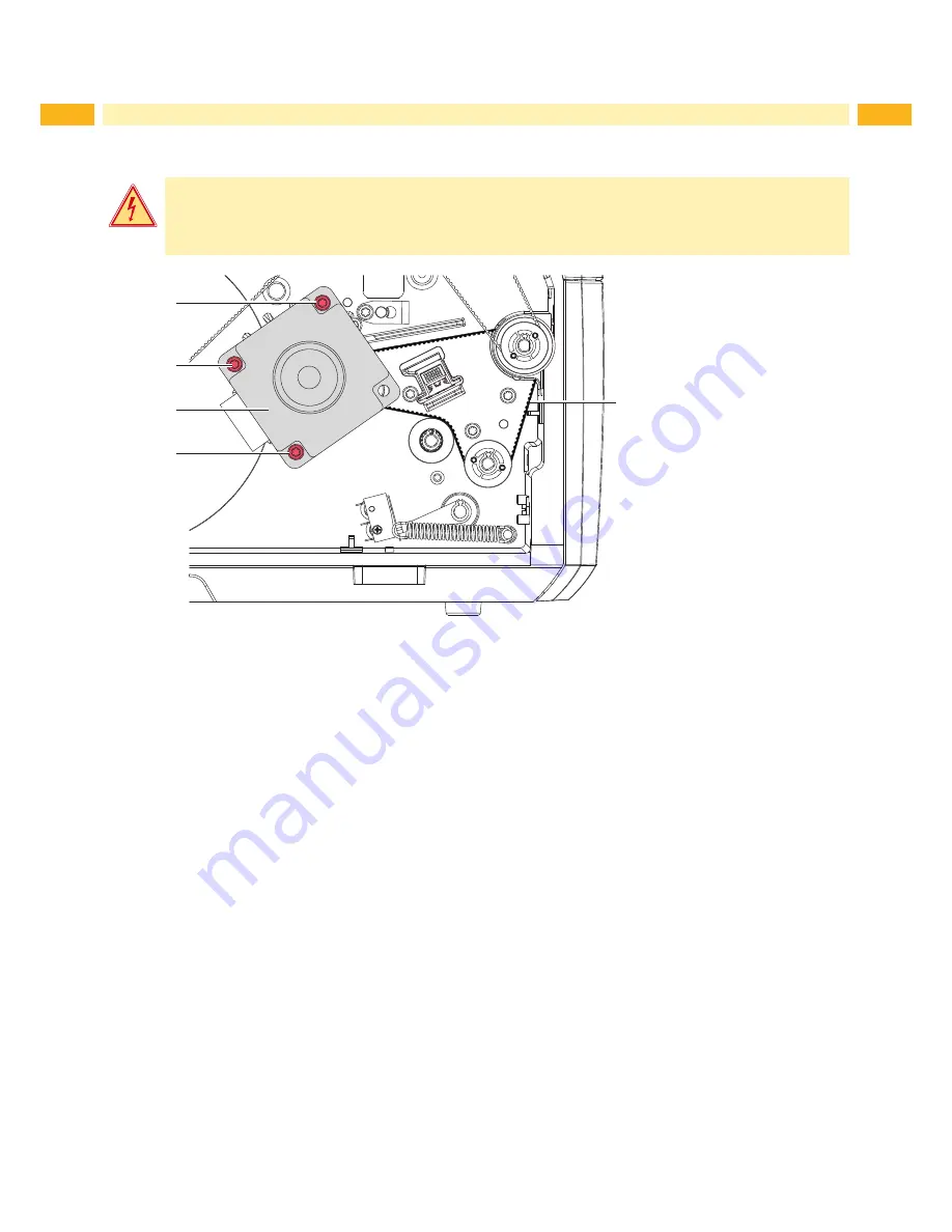
Fig. 18 

Adjusting the belt tension

1.  Unplug the printer from the electrical outlet.

2.  Remove the rear cover.

3. 

Loosen the three fixing screws (1) of the motor (2).

4. 

Swivel the motor (2) in such a way that the toothed belt (3) is tensioned tightly and tighten the fixing screws (1) in 

this position of the motor.

Summary of Contents for SQUIX

Page 1: ...Made in Germany Service Manual SQUIX Label Printer ...

Page 2: ...products discrepancies between documentation and product can occur Please check www cab de for the latest update Terms and conditions Deliveries and performances are effected under the General conditions of sale of cab Service Manual for the following products Germany cab Produkttechnik GmbH Co KG Postfach 1904 D 76007 Karlsruhe Wilhelm Schickard Str 14 D 76131 Karlsruhe Telefon 49 721 6626 0 Tele...

Page 3: ...the PCB I O Interface 15 3 Adjustments 16 3 1 Measuring and Adjusting the Winding Torques 16 3 1 1 Measuring the Winding Torques 16 3 1 2 Adjusting the Winding Torques 19 3 2 Adjusting the Printing Mechanism 20 3 2 1 Preparing the Printer for Adjustment 20 3 2 2 Adjusting the Printhead Position 21 3 2 3 Adjusting the Printhead Pressure 22 3 2 4 Adjusting the Transfer Ribbon Feed Path 23 3 2 5 Fina...

Page 4: ...r with medium risk which if not avoided may result in death or serious injury Caution Draws attention to a danger with low risk which if not avoided may result in minor or moderate injury Attention Draws attention to potential risks of property damage or loss of quality i Note Advices to make work routine easier or on important steps to be carried out Environment Gives you tips on protecting the e...

Page 5: ...ice X X Do not wear clothing with metal parts X X Do not wear jewelry X X Do not wear spectacles with metal frames Warning Items of clothing drawn into the device by moving parts can lead to injuries X X Do not wear any items of clothing which could get caught by moving parts 1 3 Protective Devices Warning There is a risk of injury if protective devices are missing or defective X X Replace all pro...

Page 6: ...ircuits in the device Test the zero potential of the device parts Check the working area for possible sources of danger such as wet floors defective extension cables defective protective conductor connections Additional precautions in the case of exposed voltages Ask a second person to remain near the working site This person must know where the emergency and power switches are and how to switch t...

Page 7: ...2 2 Replacing the Printhead The printhead of the label printer can be replaced without the need for fine adjustment The printhead must be replaced if worn or when switching to a printhead with higher or lower resolution 1 2 3 4 3 4 5 1 Data connector 2 Power connector 3 Threaded holes 4 Catching holes 5 Heating line Fig 1 Structure of the printhead Attention The printhead can be damaged by static ...

Page 8: ... First unplug the power cable 8 following the data cable 7 Mounting the Printhead 1 First connect the data cable 7 following the power cable 8 2 Place the printhead into the printhead assembly and insert the pins 9 into the holes 4 3 Press down the printhead carriage and fix the printhead with the screws 6 at the carriage using the threaded holes 3 4 Clean the heating line with the cleaning cloth ...

Page 9: ...r ribbon from the printer 4 Turn the roller bearings 5 with the 2 5 mm Allen key out of the side plate 3 5 Pull print roller 6 and rewind assist roller 4 from the shafts 1 though the side plate 3 6 Clean the shafts 1 7 Insert the new rollers 4 6 and slide them onto the concerning shaft 1 Turn the rollers slightly until the hexagonal shafts engage the hexagonal sockets of the rollers 8 Put the roll...

Page 10: ...a slipping clutch when the set value of the torque cannot be set 3 1 on page 16 Removal and instal lation of the slipping clutch is also required for replacement of a winder 2 1 3 1 Ribbon supply hub brake 2 Ribbon take up hub coupling 3 Internal rewinder coupling Fig 4 Slipping clutches Danger Risk of death via electric shock X X Before opening the housing cover disconnect the device from the mai...

Page 11: ...inder 7 11 10 9 4 12 13 4 Snap ring 7 Winder axle 9 Brake 10 Lever 11 Tappet 12 Pin 13 Spring Fig 6 Brake at the ribbon unwinder 1 Unplug the printer from the electrical outlet 2 Remove the rear cover of the printer 3 Remove the snap ring 4 4 Pull the brake 9 from the winder axle 7 Ensure that the tappet 11 remains on the winder axle Reattach the tappet to the winder axle if it has been pulled off...

Page 12: ...te until the power supply unit has discharged 1 2 3 4 5 Fig 7 Replacing the label sensor 1 Remove the rear cover 2 Remove the material from the printer 3 Disconnect the plug 2 from the label sensor 1 4 Loosen the screw 4 5 Hold pressed the knob 3 and pull the label sensor with the handle 5 out of the profile 6 Mount the new label sensor in the opposite order 7 Mount the rear cover and restore all ...

Page 13: ...external medium Configuration Manual 2 Unplug the printer from the electrical outlet 3 Detach all interface cables from the back of the printer 4 Remove all memory media from the slots 5 Dismount the rear cover 6 Unplug all plug connections 3 9 from the PCB CPU 2 7 Loosen screws 1 and remove PCB CPU 2 8 Attach the new PCB CPU 2 with four screws 1 9 Connect all cables to the PCB CPU 2 10 Mount the ...

Page 14: ... the power supply unit 1 Unplug the printer from the electrical outlet 2 Remove the rear cover 3 Dismount cover 5 control panel 4 and cover 3 4 Dismount the PCB CPU 2 6 on page 13 5 Unplug the cables from the connectors 6 7 6 Loosen 3 screws 8 7 Loosen screw 2 and remove the power supply unit 1 8 Insert the new power supply unit an fix it with the screws 2 8 9 Connect the cables at the connectors ...

Page 15: ... and wait at least one minute until the power supply unit has discharged 3 1 2 1 4 5 Fig 10 Installing the PCB I O interface 1 Unplug the printer from the electrical outlet 2 Remove the rear cover 3 Loosen two screws 1 and remove cover 2 4 Insert the PCB I O interface 3 and fix it with two screws 1 5 Connect the cable 4 to the PCB I O interface 3 and the PCB CPU 5 6 Mount the rear cover ...

Page 16: ... in both directions The measured clockwise torque is the sum of the coupling torque and the torque of the brake Only the torque of the brake is measured when the winding axis is rotating counter clockwise For this reason measurement of the torques at the rewinders are required in both directions The method of measurement differs for the various types of slipping clutches Measurement of the winding...

Page 17: ...ns supply and wait at least one minute until the power supply unit has discharged 1 Unplug the printer from the electrical outlet 2 Remove the rear cover 3 Remove the transfer ribbon from the printer 4 Attach the test collar 3 to the winder 4 5 Turn the knurled nut counterclockwise to clamp the test collar 6 Wind the cord attached to the test collar around the test collar several times 7 Secure sp...

Page 18: ...Before opening the housing cover disconnect the device from the mains supply and wait at least one minute until the power supply unit has discharged 1 1 A B 2 3 4 1 Unplug the printer from the electrical outlet 2 Remove the rear cover 3 Remove the labels from the printer 4 Push the cord 2 under a bracket 3 of the internal rewinder 4 and wind it around the rewinder 5 Secure spring scale 25 N 1 at t...

Page 19: ...the power supply unit has discharged 1 2 1 Unplug the printer from the electrical outlet 2 Remove the rear cover 3 Press the knurled ring 1 of the slipping clutch toward the housing wall The lock 2 of the knurled ring is released 4 Turn the knurled ring while pushing it and release it in the desired position 5 Ensure that the tabs of the lock are located completely in the grooves of the setting va...

Page 20: ...chanism comprises the following procedures in the order specified 1 Prepare the label printer for adjustment 3 2 1 on page 20 2 Adjust the position of the printhead 3 2 2 on page 21 3 Adjust the printhead pressure 3 2 3 on page 22 4 Adjust the transfer ribbon feed path 3 2 4 on page 23 5 Perform a final test 3 2 5 on page 23 3 2 1 Preparing the Printer for Adjustment 1 2 5 4 3 1 Load transfer ribb...

Page 21: ...djusting the printhead 1 2 5 3 4 Fig 15 Adjusting the printhead position i Note X X Open and close the printhead after each step of the adjustment 1 Loosen the screw 1 about a quarter turn 2 Align the mark 2 on the carrier plate to the pointer 4 in the printhead carriage by turning the screw 2 3 Check the printhead alignment with the test function Test grid Configuration Manual or a similar patter...

Page 22: ...lockwise until turning becomes perceptibly easy 2 Reduce the Heat level in the printer configuration until the print image is only barely recognizable Under these conditions inaccuracies become clearly visible during adjustment 3 Create print samples with the test function Test grid Configuration Manual or a similar print pattern 4 Adjust the adjustment screw 1a or 1b clockwise in small increments...

Page 23: ...k of the winder as the supply roll is from the disk of the supply hub 2 If the ribbon runs outward turn screw 3a or if the ribbon runs inward turn screw 3b clockwise in small increments Wait until the ribbon feed path has stabilized after each step of the adjustment 3 Check the ribbon feed path for wrinkles 4 If wrinkles arise on the inside turn the screw 1 counterclockwise If wrinkles arise on th...

Page 24: ...s supply and wait at least one minute until the power supply unit has discharged 1 1 1 2 3 Fig 18 Adjusting the belt tension 1 Unplug the printer from the electrical outlet 2 Remove the rear cover 3 Loosen the three fixing screws 1 of the motor 2 4 Swivel the motor 2 in such a way that the toothed belt 3 is tensioned tightly and tighten the fixing screws 1 in this position of the motor ...

Page 25: ...e cable and replace it if necessary If all functionality of the interface has been lost replace the PCB CPU A peripheral device is not functioning Check whether the peripheral device is activated via programming Check the USB cable of the peripheral device and replace it if necessary Check the peripheral device Replace the PCB CPU Table 3 Failure of device functions 4 2 Permanent Hardware Faults E...

Page 26: ...26 26 5 Block Diagram Printer No 1 Printer No 2 SQUIX 4 P 5977331 SQUIX 4 300 5977444 SQUIX 4 T 5952598 SQUIX 4 600 5977380 SQUIX 4 3 200 5977382 SQUIX 4 3 300 5977383 Fig 19 Block diagram ...

Page 27: ... M C2 C28 C163 AC D14 R71 CON4 R108 V R136 C187 C307 R166 1 L90 V13 V7 C164 C5 5 R280 F R77 C308 L25 R160 C213 C160 15 C207 2 R253 V21 R139 C42 C204 1 R163 C169 L42 L80 TOP6 C268 CON17 10 C15 R209 R78 C271 3 L14 FD3 C170 N1 R98 C196 20 1 P4 CON9 C225 C209 C309 1 U4 R171 L66 H1 R31 C171 K 8 L1 C313 25 R85 E C310 T R172 K B5 C27 C351 C172 R150 L30 C352 L R2 C325 C220 C311 L59 R227 V9 C168 AA C112 7 ...

Page 28: ...ent 13 Power supply replacement 14 Power supply unit 14 Printhead position 21 Printhead pressure 22 Printhead replacement 7 Print image 20 Printing mechanism 20 Print roller replacement 9 Protective devices 5 R Rewind assist roller replacement 9 Rewinder 17 18 S Slipping clutches Adjustment 19 Replacement 10 T Test collar 16 Tools 7 Torque 16 18 Transfer ribbon feed path 23 U Unwinder 17 V Voltage...

Reviews: