background image

12

Operation

If the device switched of an d on it' will start in the last program before switched off.

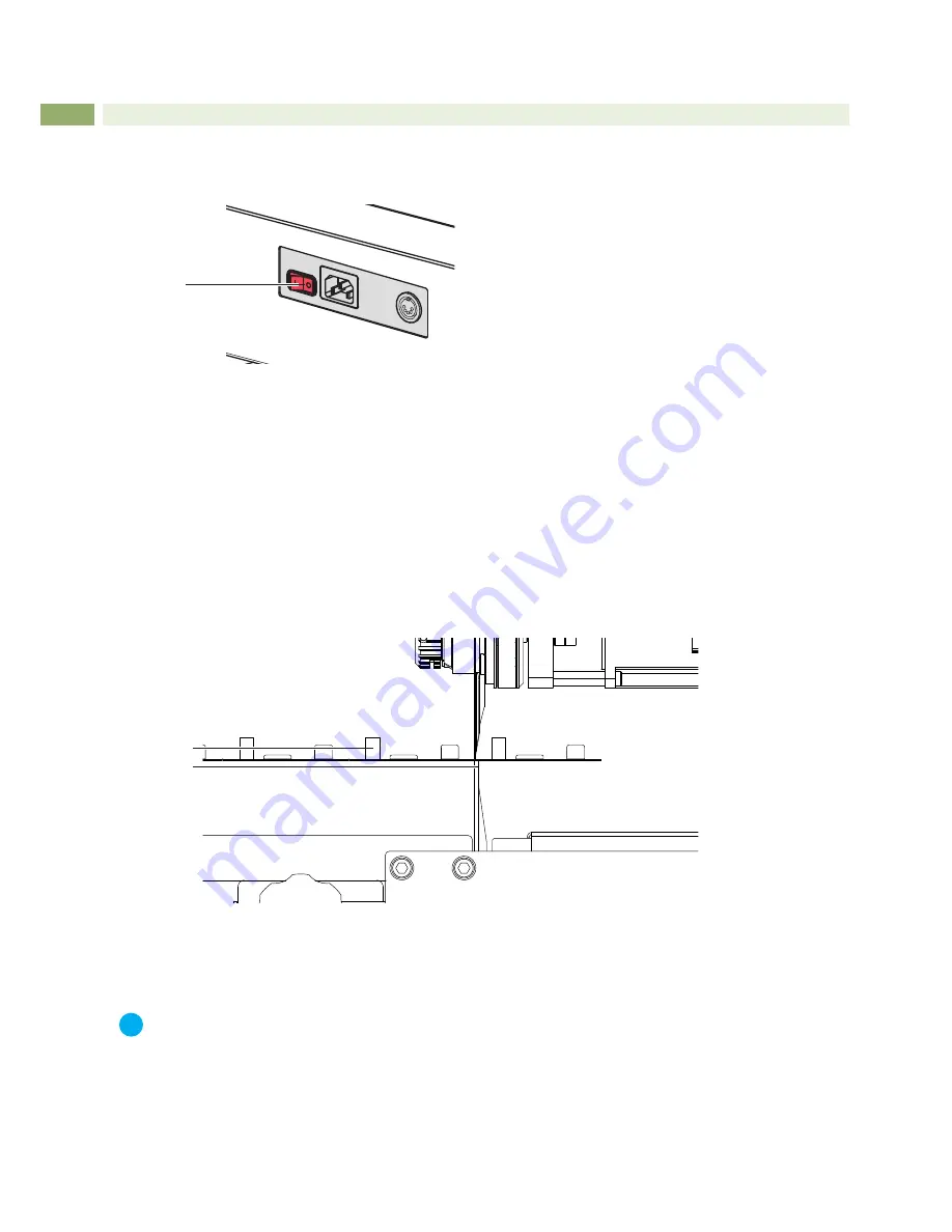
Switch on the device by the power-switch (1). LED not ready blinking. 
 

1


Fig.8     

Power Switch 

1.  Press button 

home

.

2.  Press the foot-switch and hold it. 

- Device will run to the start position or from the start position short out and back into the start position.. 
- Synchronization of the blades.

3.  Deblock the foot-switch - device is ready for operation. LED

 not ready

 don't glow. 

4. 

Select program. If you switch of and on, the last used program is selected. After first switch on program 1 is 

selected.

5.  Put in the PCB panel. 

Pre-scored groove in the PCB (2) put onto the linear blade (3) and hold the PCB in the horizontal plane by hand. 
Ensure that the PCB is positioned within the area between the green knurled screws, the pre-selected area of 
cutting way of the upper blade. 

2

3

Fig.9     

Put in PCB

6.  Press the foot-switch to start the program. Foot-switch must be pressed over the length of the program.

7.  Deblock the foot-switch after program end. 

i

Notice! 
In case of uneven number of cuts will be an other start position for the next program start. 

Reset the display of cut length


Press button 

DEL for 

3


seconds. 

Display 

mileage

 blinking.


In the next 3 seconds press button 

DEL 

again to reset the display to Zero.

Summary of Contents for MAESTRO 4S

Page 1: ...Operator s Manual MAESTRO 4S PCB Separator ...

Page 2: ...e latest update Terms and conditions Deliveries and performances are effected under the General conditions of sale of cab Operator s Manual Translation of the Original Version for the following products Germany cab Produkttechnik GmbH Co KG Postfach 1904 D 76007 Karlsruhe Wilhelm Schickard Str 14 D 76131 Karlsruhe Telefon 49 721 6626 0 Telefax 49 721 6626 249 www cab de info cab de France cab tech...

Page 3: ...onize the blade 9 6 2 Programming 9 6 3 Recommendation for cutting depend of notch thickness and number of cuts 10 6 4 Changing the Program 11 7 Adjustment the Cut Length 11 8 Operation 12 9 Maintenance 13 9 1 Changing the Upper Blade 13 9 2 Adjustment of the Upper Blade Stopper 14 9 3 Upper Guide Adjustment 15 9 4 Table Adjustment 15 9 5 Changing the Linear Blade 16 9 6 Adjusting the Linear Blade...

Page 4: ...arating pre scored PCB s Any other use or use going beyond this shall be regarded as improper use The manufacturer supplier shall not be liable for damage resulting from unauthorized use the user shall bear the risk alone Usage for the intended purpose also includes complying with the operating manual including the manufacturer s maintenance recommendations and specifications i Notice The complete...

Page 5: ...Danger Danger to life and limb from power supply X X Do not open the device casing 1 4 Safety Marking 4 3 2 1 Fig 1 Safety marking 1 Emergency Switch X X Press it in a hazardous situation 2 Risk of hand injury X X Wear protective gloves while PCB separating 3 Possible damage of electronics X X Disconnect the PCB separator from the electrical outlet before mounting or removing an optional conveyor ...

Page 6: ...ase of programming Mileage Kilometer counter up to 99 99 km DEL Reset of the kilometer counter Power switch ON OFF Foot switch START Separation Safety switch Emergency stop Spannung 100 240 V 50 60 Hz Emission sound pressure level LpA 70 dB A Temperature humidity not condensing Operation 10 35 C 10 85 Stock 20 50 C 20 80 Transport 25 50 C 20 80 Weight 38 kg 46 kg Height Depth 434x425 mm Width 702 ...

Page 7: ...nchronization of thr blade 3 Button speed Choice of speed 4 Display speed Display the selected speed L Low and H High 5 Button program Program choice 6 Display program Display the selected program 7 Button step Choice the cut of the material separation in the program 8 Display step Show the current cut in the operation Show the selected cut in the program 9 Button distance Make the distance betwee...

Page 8: ...ct the power cable 5 to the power input module 3 and to an earthed socket 5 2 Assembly of the Adjustable Platform 2 1 3 4 Fig 5 Assembly of the adjustable platform The adjustable platform delivered with the machine is designed for use as a hand rest easing the placement of the PCB on the lineal blade Thereby it is also preventing a possible premature tiring for the user The adjustable platform is ...

Page 9: ... increasing cut deepness respectively declining blade distance 1 cut blade distance 0 6 mm 2 cut blade distance 0 3 mm 3 cut blade distance 0 mm 6 2 Programming 1 Press button program and hold it over 3 seconds The display of the selected program is blinking 2 Select desired program place by the button program 3 Press the button key for 3 seconds up to the LED key is blink 4 Select cut step by the...

Page 10: ...0 25 mm 1 0 35 mm Notch Thickness 0 6 mm Number of cuts to separating PCB s 1 Cut 2 Cut 3 Cut 4 Cut 5 Cut 5 0 50 mm 0 35 mm 0 25 mm 0 10 mm 0 00 mm 4 0 50 mm 0 30 mm 0 15 mm 0 00 mm 3 0 45 mm 0 30 mm 0 15 mm 2 0 40 mm 0 20 mm 1 0 30 mm Notch Thickness 0 5 mm Number of cuts to separating PCB s 1 Cut 2 Cut 3 Cut 4 Cut 5 Cut 5 0 40 mm 0 30 mm 0 20 mm 0 10 mm 0 00 mm 4 0 40 mm 0 25 mm 0 15 mm 0 00 mm ...

Page 11: ... 2 complete loosen it only easy 2 Activate the foot switch to start and run the program one times The carriage will be now in a Endposition and the lower blade is free 3 Hold the PCB on an any position between the both knurled screw 4 Move the knurled screws 1 and 2 to the outside edges of the PCB and tighten the screws i Notice The distance between the knurled screws 1 and 2 must be 20mm minimum ...

Page 12: ...first switch on program 1 is selected 5 Put in the PCB panel Pre scored groove in the PCB 2 put onto the linear blade 3 and hold the PCB in the horizontal plane by hand Ensure that the PCB is positioned within the area between the green knurled screws the pre selected area of cutting way of the upper blade 2 3 Fig 9 Put in PCB 6 Press the foot switch to start the program Foot switch must be presse...

Page 13: ...4 Swing lever 6 in position a to decouple 5 Loosen screws 4 and remove table 1 by movements back and top 6 Loosen screws 8 7 Remove motor carriage with mounted motor 7 8 Hold the setting knob 5 and loosen the knurled nut 12 9 Remove blade 11 It s possible that the washer 10 are adhere on the blade Remove the Washer 10 from bladeand take it back on the axle 9 10 Take the new blade 11 on the axle 9 ...

Page 14: ...rive to the blade carrier 1 is now disconnected 2 Rotate the pointer 2 with the knob 4 counterclockwise to position 16 3 Move the upper blade carrier 1 in the middle position of the lower blade 4 Loosen the screw 3 5 Move the knob 4 clockwise until the upper and lower blades are in a distance of 0 03 mm Use a thickness gauge 6 Swing the strut 5 clockwise until you reach the stop and tighten the sc...

Page 15: ...uit the MAESTRO 4M to differing requirements the height of the table can be adjusted as follows 1 Loosen the knurled screws 7 located on the inner side of the machine frame 2 Lift the table 5 slightly and move it towards the rear until the stop 3 Slide the table on the slots 6 and mount it at the height required 4 Pull the table gently forwards until it locks into place 5 Tighten the knurled screw...

Page 16: ...ont view inclined Fig 15 Changing the linear blade Bottom view inclined 1 Loosen shouldered screw 4 2 Hold the linear blade 1 to avoid an uncontrolled fall of the blade 3 Loosen screws 3 The eccentric 2 will used for guiding and will not loosened 4 Pull out the linear blade 1 in direction of the device rear side from eccentric 2 5 Move out the linear blade 1 6 Mounting of the new linear blade in r...

Page 17: ... blade by the setting knob on the carriage 1 3 Pull the carriage 1 over the full cutting length The Distance between upper blade and linear blade 2 must be constant over the full length 4 Repeat this activity with reduced distance between upper blade and linear blade 2 up to a possible variation in the distance is visible 5 Are variation in the distance visible loosen screws 5 6 Turn the eccentric...

Page 18: ... 2 mm of the edge of the blade Rotate the scale on the dial gauge until the pointer in the 1 100 mm division is lined up with the 0 on the scale 4 Swing the lever 6 downwards until the tip of the gauge feeler 7 presses onto the lower blade 10 at 2 mm of the edge of the blade 5 In the event of the values obtained by the above procedure being greater than the values the servicing agent responsible f...

Page 19: ...ting length 10 Errors Cause of error Effect Display Error recovery The food switch is clear in the moment of synchronization LED not ready Display step Display distance Display cut length blink X X Switch of the device and switch it on again X X New synchronization The device is switched on and the carriage with the upper blade will moved by hand out of the start position The carriage with the upp...

Page 20: ...ves and Standards Directive 2006 42 EC on machinery EN ISO 12100 2010 EN ISO 13857 2008 EN 349 1993 A1 2008 EN 60204 1 2006 A1 2009 EN 61029 1 2009 A11 2010 Directive 2014 30 EU relating to electromagnetic compatibility EN 61000 3 2 2014 EN 61000 3 3 2013 EN 61000 6 2 2005 EN 61000 6 4 2007 A1 2011 Directive 2011 65 EU on the restriction of the use of certain hazardous substances in electrical and...

Reviews: