7
2.3
Overview
ort air
vacuum
14
15
5
9
11
4
y
x
z
1
2
3
10
12
7
8
13
6
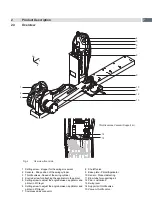
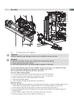
Fig. 2
Overview front side
1 Setting screw - stopper for the swing movement
2 Sensors - End position of the swing cylinder
3 Throttle valves - Speed of the swing cylinder
4 Knurled screw for attaching the applicator to the printer
5 Setting screw to adjust the angle between applicator and
printer in X/Y-layer
6 Setting screw to adjust the angle between applicator and
printer in Z/X-layer
7 Compressed air connector
8 Shutoff valve
9 Base plate - Printer/Applicator
10 Sensor - Product detecting
11 Blow tube for supporting air
12 Pad - customized
13 Swing lever
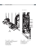
14 Support air throttle valve
15 Vacuum throttle valve
Throttle valves Vacuum/Support air


