background image

WHITE POOL INSTRUCTION MANUAL


pag. 18 / 29


www.cpa-piscine.it


Rev.00

16/10/20 


VI.


Assembling the pool base rails 

Cover the ground with a levelled layer of sand and lay the ground sheet (3).  
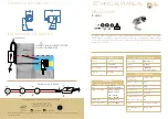
Unpack all of the components and check the parts against the checklist. Slide the bottom rail into the metal piece. 

Important: leave about 1 cm between the 2 ends of the bottom rail. 

Repeat this process for all bottom rails (see diagram 17). 


Diagram 17 

Item No. 

Description 

Pool dimension (mm) 

8011015


White Pool 490 

L4900 x W3600 x H1300


Item No. 

Description 

Pool dimension (mm) 

8011012


White Pool 610 

L6100 x W3600 x H1300


Item No. 

Description 

Pool dimension (mm) 

8011013


White Pool 730 

L7300 x W3600 x H1300


Item No. 

Description 

Pool dimension (mm) 

8011014


White Pool 910 

L9100 x W4600 x H1300


9A

9A

9A

9A

9A

9A

9A

9A

9A

9A

9A

9B

9A

9A

9A

9A

9A

9A

9A

9A

9A

9A

9B

9B

9B

9B

9C

9C

9C

9C

9C

9C

9C

9C

9C

9C

9C

9C

9C

9C

9A

9A

9A

9A

9A

9A

9A

9A

9A

9A

Summary of Contents for White Pool 490

Page 1: ...WHITE POOL INSTRUCTION MANUAL pag 1 29 www cpa piscine it Rev 00 16 10 20 C P A S R L WHITE POOL Assembly and maintenance guide READ CAREFULLY THIS MANUAL AND RETAIN FOR LATER REFERENCE...

Page 2: ...assembled frames 16 VI Assembling the pool base rails 18 VII Fine adjustment of the bottom rails diameter 19 VIII Fixing the pool wall 20 IX Measuring the pool wall 21 X Making a protective sand cush...

Page 3: ...Warning Water attracts children always remove pool ladder when not in use Store in a place not accessible to children Danger Prevent the risk of accidental drowning Extreme caution must be exercised...

Page 4: ...ified persons Warning Do not burry electric cord Avoid using lawn mowers hedge trimmers and other garden equipment near or around the metal wall pool and electrical cord Warning Never swim or bathe in...

Page 5: ...immer box manual bottom rail fix rail round rail protector plug upper joint protector top bottom metal piece adhesive tape nut M6 washer M6 bolt M6 x 11 bolt M4 x 10 nut M12 washer M12 bolt M12 x 24 b...

Page 6: ...0 0 16 10 Fix rail 1380mm length 11 11 11 0 Fix rail 1270mm length 0 2 4 0 Fix rail 1460mm length 0 0 0 17 11 Round rail 1380mm length 11 11 11 0 Round rail 1270mm length 0 2 4 0 Round rail 1460mm le...

Page 7: ...thes pegs Sharp knife Spirit level Site excavation tools Protective gloves Pre cast cement block ACCEPTABLE Flat level firm and dry ground with easy access to all sides of the pool exposed to direct s...

Page 8: ...INSTRUCTION MANUAL pag 8 29 www cpa piscine it Rev 00 16 10 20 PHASE 2 Pool setup I Ground preparation The preparation of the ground is the most important step in the installation of the pool Diagram...

Page 9: ...tring onto the stick At the other end of the string tie a funnel The distance between the stick and the funnel should be 150 mm more than the radius of the pool see diagram 3 Diagram 3 3 Place flour o...

Page 10: ...the pool collapse due to unlevelled ground it could cause a lot of damage to property and even human injury or death Diagram 5 Remove the higher ground rather than filling the low laying ground see di...

Page 11: ...sed for below items Diagram 8 See diagram 9 the same L support 21 fixing plate 22 and connection plate 23 are used for below items Diagram 9 Item No Description Pool dimensions mm 8011015 White Pool 4...

Page 12: ...ave been correctly assembled and all of the nuts and bolts have been tightened it s time to position the assembled frames onto the pool site Please refer to the layout size of pool you have purchased...

Page 13: ...sembled frame upright across the width of the pool at a point 2450 mm from the end of the cleared area Place the 2nd and the remaining assembled frames at a point 1200 mm from the center line of the a...

Page 14: ...he assembled frames position string line along the back of the assembled frames the back of the L support about 200 mm above the ground between two steel pegs position A and B as shown in diagram 15 I...

Page 15: ...ix instead of concrete blocks the cement mix is put in place after the assembled frames have been positioned and leveled Concrete pads the use of concrete blocks or concrete mix at each end of the ass...

Page 16: ...are all correct and equal Before proceeding check the measurements for the width of the pool between the inside of the assembled frames should be as per table below The width measurements A can have...

Page 17: ...WHITE POOL INSTRUCTION MANUAL pag 17 29 www cpa piscine it Rev 00 16 10 20 Place the pre cast concrete blocks under the L supports...

Page 18: ...m rail Repeat this process for all bottom rails see diagram 17 Diagram 17 Item No Description Pool dimension mm 8011015 White Pool 490 L4900 x W3600 x H1300 Item No Description Pool dimension mm 80110...

Page 19: ...s are slided into the metal pieces it should form a complete circle and the diameter should be equivalent to the diameter of the pool itself You can shorten or lengthen the gap distance between the 2...

Page 20: ...and filtration system should be placed The opening end of the pool wall closest to the square window should be placed on the closest metal piece to your selected location for the electric supply of t...

Page 21: ...more than 2 cm see diagram 23 then the ground site must be levelled again Check also if the pool is oval and measure the diameter across a few spots to make sure the differences of each diameter meas...

Page 22: ...tend it evenly until the seam line reaches the base of the pool where the protective sand cover is Smooth out all the wrinkles in the liner Straighten the PVC liner and hold it perpendicular to the gr...

Page 23: ...one at time whilst applying the fix rails see diagram 32 Connect another fix rail continue around the circle until all fix rails are all joined together And finally apply the round rails to the fix r...

Page 24: ...on the end of the vertical support 7 Drive the bolts 19 into the sides and front of the vertical support 7 so that it passed through with the hole in the top bottom metal piece 14 tabs Repeat this pro...

Page 25: ...h using four bolts Continue this process until all of the resin top platforms are attached to all of the metal pieces at the top see diagram 36 Check the alignment but do not tighten Diagram 36 Fix al...

Page 26: ...s are for sealing the edges of the resin top platforms Hook the cover over the inside edge of the resin top platforms and gently pull to fasten the cover to the outside edge Fix with the screws provid...

Page 27: ...and lower rails Check for rips tears holes and repair where necessary Check for damaged for broken platforms repair where necessary Pool liner Top platform Top and bottom metal piece Top and bottom ra...

Page 28: ...tering the skimmer box opening WARNING To avoid collapse never leave the pool without water in it Diagram 43 WARNING The filter pump must be switched off if there are swimmers inside the pool Follow a...

Page 29: ...on system on at least one day before using the pool Allow enough time to ensure the pool water is completely filtrated before use 6 Make sure the water level is 15cm 6 from the top Note The informatio...

Page 30: ...SAND FILTER INSTRUCTION MANUAL pag 1 di 8 www cpa piscine it Rev 01 26 04 21 C P A S R L SAND FILTER Installation and maintenance manual READ CAREFULLY THIS MANUAL AND RETAIN FOR LATER REFERENCE...

Page 31: ...ly In addition the connections must conform to the directive VDE 1 No reclamation will be accepted for the consequences resulting from an incorrect installation or start up or for non compliance with...

Page 32: ...tion Before installing the filter pump unit identify the position in which it is to be installed as once it has been filled up with sand the filter is hard to move due to its weight The filter plug is...

Page 33: ...haped gauze is well centralized in the bottom of the filter and that the purge screw is tight 3 Place the spigot on the mouth of the container making sure the tube is centered on the manifold 4 Fill t...

Page 34: ...of the pre filter of the pump until the water enters the pre filter 4 Place the valve selector in position COUNTERWASH Only this can the pump be started Begin a cycle of COUNTERWASH of 2 to 3 minutes...

Page 35: ...d finally expelled outside the door D Rinse This function is used for initial start up cleaning and leveling of the sand bed after backwashing water is pumped down through the sand bed pushed up throu...

Page 36: ...t be completely full of water so the pump does not suck air when this is done the pump can be started If air enters the monobloc stop the pump and purge the floor cleaner Start the pump again slowly a...

Page 37: ...er Damage caused by freezing is not covered by the guarantee Maintenance suggestions The visible impurities are eliminated by the monobloc What the monobloc does not eliminate are the algae bacteria a...

Page 38: ...LEAF SKIMMER MANUAL pag 1 di 3 www cpa piscine it Rev 00 16 10 20 C P A S R L LEAF SKIMMER Instruction manual READ CAREFULLY THIS MANUAL AND RETAIN FOR LATER REFERENCE...

Page 39: ...6 10 20 Components N Description Quantity 01 Hose attachment 1 02 Cover 1 03 Basket 1 04 Skimmer housing 1 05 Weir 1 06 Gasket 2 07 Face plate cover 1 08 Screw ST5 5x25 10 09 Skimmer conncector 1 10 I...

Page 40: ...d tighten the screws into position but do not over tighten as you may damage the screws and or the pool wall and liner Do not create multiple holes as this will cause damage to the pool wall and pool...

Reviews: