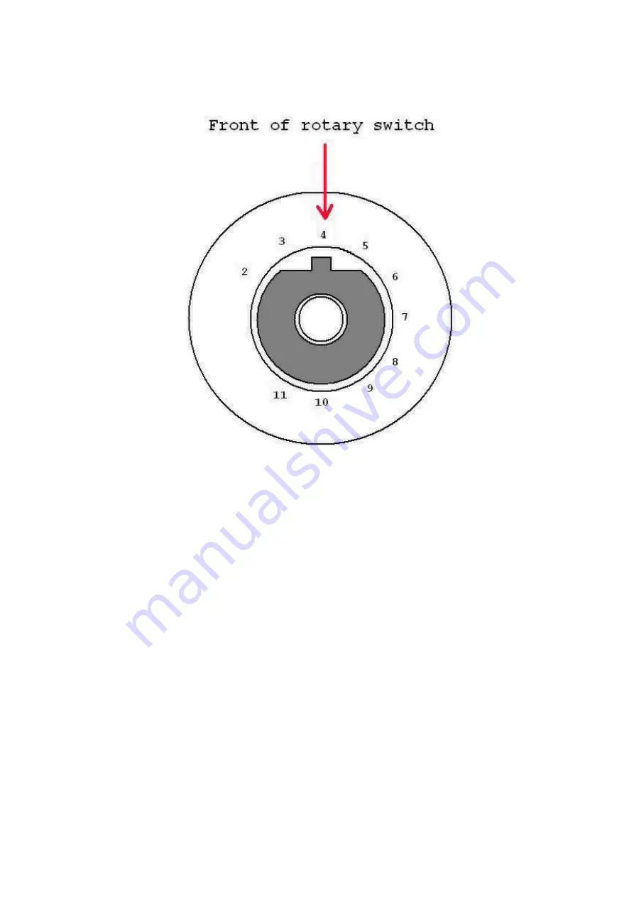
On the front of you rotary switch is a washer. And this washer has a notch on it. This washer
limits the number of positions you can turn your rotary switch to by placing the washer's notch
in the appropriately numbered hole. We want to set our switch for 4 positions so we want to
put the washer's notch into hole #4.
Step1: Install and solder the rotary switch ON THE BACK SIDE OF THE PCB!!!!
Step 2: Install and solder the pots ON THE BACKSIDE OF THE PCB!!! If your kit came
with solder lugged pots, skip this step and go complete the assembly and wiring portions
of the instructions. Then continue here with Step 3.
Step 3: Insert the LED into it's place, but do not solder it yet. Make sure the longer lead goes
in the round solder pad and the shorter lead goes in the square solder pad. No....this is not a
typo.
Step 4: Mount the entire circuit board assembly inside the enclosure. Makes sure you have the
spacer nuts on your PC mounted pots(no spacers required for solder lug pots), and make sure
that the Rotary switch limit washer hasn't fallen out of place. Then secure the pots and rotary
switch with their nuts and washers.
Step 5: Move the LED into place by guiding it with the leads that are sticking out of the top
side of the PCB.
Step 6. Once you have the LED in place, solder it and clip the excess leads.


