background image

Step 2:  Install the LED/Bezel assemblies in the enclosure.  These will be a very tight fit,

but trust us...you want them to be.  Push the bezel into their respective holes through the

top of the enclosure with your thumb.  You will feel them snap into place.  Orient the

LED/Bezel assemblies so that the anodes are facing the jack side of the enclosure and the

cathodes are facing the footswitch side of the enclosure.

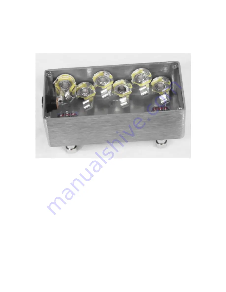
Step 3:  Install the Jacks.  Notice how all of the mono jacks are rotated slightly.  This is to

insure that there are no bare metal contacts touching any other bare metal contacts.  Use

common sense when installing the jacks.  If you see contacts from two jacks touching.

Rotate one or both slightly so that there is no contact.  Once you have all the jacks in

place, use a 3/8  wrench or socket to tighten.

Summary of Contents for A/B True Bypass Looper

Page 1: ...be free of typos or minor errors BYOC LLC does not warranty the completed pedal as a whole functioning unit nor do we warranty any of the individual parts once they have been used If you have a compon...

Page 2: ...nge and please title your thread appropriately If everyone titles their threads HELP then it makes it impossible for the people who are helping you to keep track of your progress A very brief discript...

Page 3: ...A B TRUE BYPASS LOOPER KIT INSTRUCTION INDEX Parts Checklist page 4 Assembly page 5 9 Wiring page 10 18 Operating Overview page 19 Schematic page 20...

Page 4: ...sistors 3 4k7 yellow purple black brown brown Diodes 3 5mm LEDs Red Yellow and Clear Blue Hardware 1 drilled enclosure w 4 screws 2 3PDT footswitch 3 LED bezels 1 AC adaptor jack 5 mono jack 1 stereo...

Page 5: ...t the LEDs into their Bezels You will need to push very hard Use a pair of pliers to hold the legs of the LED while pushing You will feel it snap into place Do not try to use your fingers You will onl...

Page 6: ...are facing the jack side of the enclosure and the cathodes are facing the footswitch side of the enclosure Step 3 Install the Jacks Notice how all of the mono jacks are rotated slightly This is to ins...

Page 7: ......

Page 8: ...Step 4 Install the footswitches Notice that the A B footswitch is rotated a 1 4 turn Below is the numbering system used to differentiate the solder lugs on a 3PDT footswitch...

Page 9: ...Step 5 Install the DC Adaptor Jack Be sure to orient the jack so that the tip is facing up as seen in the pics...

Page 10: ...the cathode negative lead or shorter lead of the Blue LED to LUG1 of the bypass footswitch Connect the cathode of the Red LED to LUG3 of the A B footswitch and the cathode of the Yellow LED to LUG1 o...

Page 11: ...h bare metal Keep this in mind when bending leads and measuring before clipping components If you do have an area where bare metal is touching or an area that you feel will cause problems in the futur...

Page 12: ...low and red LEDs Trim the excess component lead of the resistors that is connected to the LEDs The clip and bend the other end of both resistors to form a solder terminal the same way you did with the...

Page 13: ...to the tip The red wire connects to the disconnect terminal of the sleeve Connect the ring of the input jack to the tip of the DC adaptor jack Since there will be two wires going into the tip of the D...

Page 14: ...B footswitch NOTE Wiring step 5 this way will leave on of the A B status lights constantly lit even when the looper is in bypass This way you know whether you are in loop A or loop B before you engag...

Page 15: ...footswitch Connect the tip of the output jack to LUG8 of the bypass footswitch Jumper LUGS 3 6 of the bypass footswitch and LUGS 4 9 of the bypass footswitch Since 2 connections will be made at LUG4 i...

Page 16: ...Step 7 Connect LUG7 of the bypass footswitch to LUG5 of the A B footswitch Connect LUG5 of the bypass footswitch to LUG8 of the A B footswitch...

Page 17: ...B jack to LUG9 of the A B footswitch Connect the tip of the Return B jack to LUG6 of the A B footswitch Connect the tip of the Send A jack to LUG7 of the A B footswitch Connect the tip of the Return A...

Page 18: ...our bypass looper If everything works the way it s supposed to use the cable tie to bundle your wiring If it s not working correctly trouble shoot your build and getting working properly before you ti...

Page 19: ...s not engaged your signal bypasses the fx loop and goes straight from the input jack to the output jack An A B box has in input and an output A and an output B It basically takes your input signal and...

Page 20: ......

Page 21: ...Please visit http buildyourownclone com board for any technical support copyright 2010 B Y O C LLC...

Page 22: ...f the A B footswitch to lug 1 of the bypass footswitch Do not connect lug 2 of the A B footswitch to the sleeve of the out jack Keep in mind that the cathode of the bypass status LED will already be c...

Reviews: