Step 2:
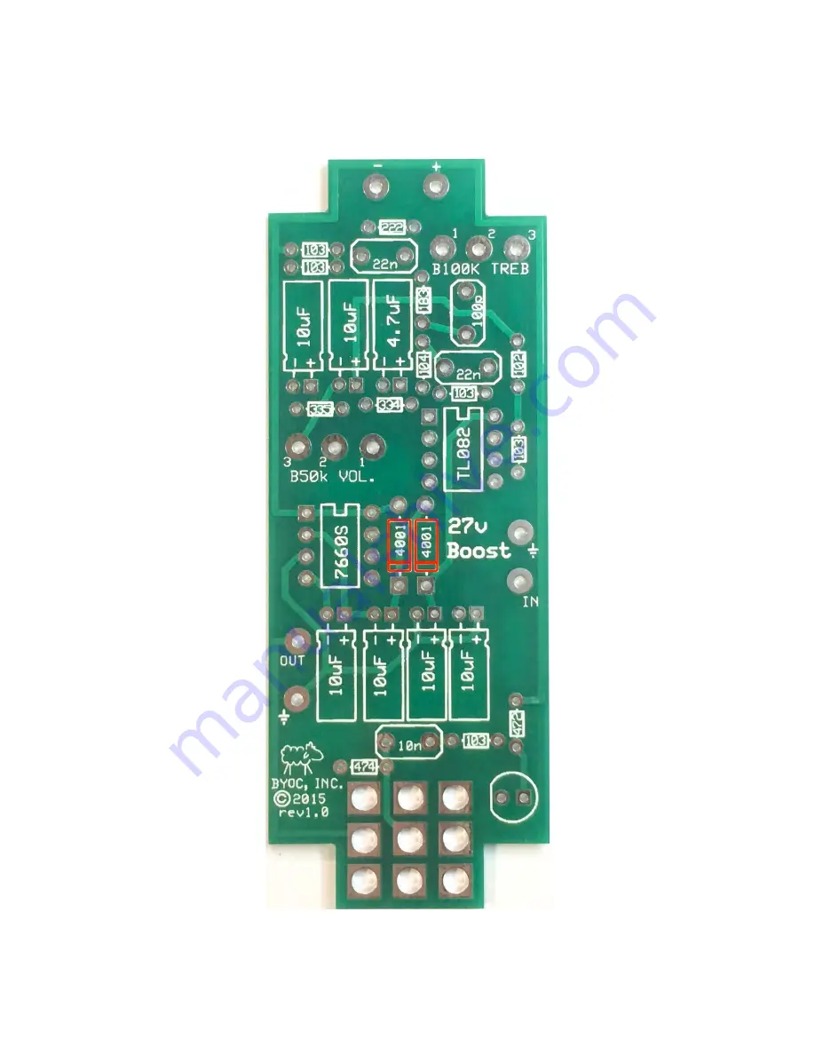
Add the diodes. Be sure to match the end of the diodes with the
stripe to the layout on the PCB. The striped end should go in the square solder pad.
Page 1: ...anty any of the individual parts once they have been used If you have a component that is used but feel it was defective prior to you using it we reserve the right to determine whether or not the comp...
Page 2: ...ryone titles their threads HELP then it makes it impossible for the people who are helping you to keep track of your progress A very brief description of your specific problem will do It will also mak...
Page 3: ...27V Boost Kit Instruction Index Parts Checklist page 4 Populating the Circuit Board page 6 Enclosure Hardware Assembly page 11 Wiring page 16 Operation Overview page 20 Schematic page 21...
Page 4: ...474 Yellow Purple Black Orange Brown Yellow Purple Yellow Gold 1 3M3 335 Orange Orange Black Yellow Brown Orange Orange Green Gold Visit www byocelectronics com resistorcodes pdf for more information...
Page 5: ...rdware 1 predrilled enclosure w 4 screws 1 27V Boost circuit board 1 3pdt footswitch 1 LED 1 External nut AC Jack 2 Enclosed Audio Jacks 4 rubber bumpers 2 lock washers for in and out jacks hook up wi...
Page 6: ...Populating the Circuit Board Step 1 Add all the resistors Resistors are not polarized and can be inserted in either direction...
Page 7: ...Step 2 Add the diodes Be sure to match the end of the diodes with the stripe to the layout on the PCB The striped end should go in the square solder pad...
Page 8: ...ient them correctly There may be a U shaped notch on the IC between pins 1 and 8 Line that up with the screenprint on the PCB If your IC does not have a notch look for a dot to indicate pin 1 Pin one...
Page 9: ...Step 4 Add the film and ceramic disc capacitors These are non polarized and can go in either direction The ceramic disc capacitor is highlighted in yellow...
Page 10: ...s a positive and negative end The positive side will have a longer lead and goes in the square solder pad The negative side will have a shorter lead and a stripe running along the body of the cap and...
Page 11: ...Enclosure Hardware Assembly Step 1 Mount the DC adapter jack...
Page 12: ...meters You will mount them opposite each other so that when looking into the enclosure the right potentiometer will have its lugs facing towards the ac jack and the left potentiometer will have its lu...
Page 13: ...corner of the jack are facing away from each other If looking at the inside of the enclosure the OUTPUT jack will have its sleeve terminal facing towards the AC jack The INPUT jack will have its sleev...
Page 14: ...the solder lugs are like the diagram below NOTE There are no actual number markings on the footswitch There are two correct ways you can orient the footswitch They are both 180 degrees of each other E...
Page 15: ...FOOT SWITCH SOLDER LUG DESIGNATIONS...
Page 16: ...ions to the back side of the PCB and solder on the top screen printed side of the PCB Make the wires as short as possible but allow enough length so that if you need to do any trouble shooting later y...
Page 17: ...otentiometers and IN OUT jacks are wired insert the LED in its hole Insert the long lead into the square hole You might want to slightly bend the leads away from each other to keep them in the holes f...
Page 18: ...closure and place the PCB onto the footswitch DO NOT SOLDER YET It is extremely important that when you place the PCB on the footswitch you make sure to tuck all the wires out of the way so that that...
Page 19: ...tion of the PCB so that it fits correctly reheat the single solder joint you just made on the footswitch Adjust the position of the PCB while the keeping the solder joint hot Remove the heat and hold...
Page 20: ...l output volume TREB Cuts or boosts frequencies over 2 2KHz Clockwise boosts Counter Clockwise cuts Noon on the dial is flat EQ response Power supply 2 1mm negative tip Current Draw 15mA Input Impedan...
Page 21: ......
Page 22: ...Please visit http byocelectronics com board For any technical support Copyright 2015 BYOC Inc...