background image

make adjustments before mounting the sight on the fi rearm. Be sure to check that the mount and the 

sight remain fully secured after the fi rst 2 to 3 shots. 


CAUTION

-When  a  sudden  increase  in  resistance  in  the  adjustment  screw  is  felt,  the  end  of  the 

    adjustment range has been reached.  DO NOT try to turn the adjustments any further or damage 

    may occur to the sight. 

8

9

BORE SIGHTING AND ZEROING


Bore sighting is a good preliminary procedure in achieving proper alignment of your sight to the fi rearm. 

If the sight is to be mounted to a Weaver-style rail, it is imperative that the base be parallel to the bore.  

Any major elevation adjustments may be accomplished by shimming the Weaver-style rail. It is important 

not to use the elevation adjustment of the sight for major adjustments.  The sight’s elevation and windage 

adjustments should be used only for fi ne-tuning to achieve zero at the desired shooting distance.  Final 

zeroing of your fi rearm and sight should be done with live ammunition. 

WINDAGE AND ELEVATION ADJUSTMENTS


The Bushnell® Holosight® XLP has rotating adjustment features for elevation and windage adjustments.  

The feature at the back of the sight is the elevation adjustment and the feature at the front side of the sight 

is the windage adjustment.  Both of the adjustment features have a slotted head that requires the use of a 

screwdriver, coin, or similar tool to rotate. 

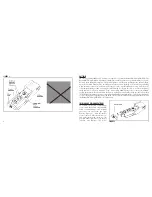
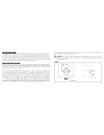
The elevation and windage adjustments are shown in Figure 5. For  both elevation and windage, each 

click will change the bullet’s point of impact 1/2 Minute of Angle (MOA), which translates to 1/4 inch at 

50 yards, 1/2 inch at 100 yards.  Also, one full rotation of either knob will change your point of impact 

15 MOA. This translates into 8 inches at 50 yards, 15 inches at 100 yards. To move the point of impact 

UP, turn the adjustment counterclockwise; to move the point of impact DOWN, turn the adjustment 

screw clockwise. To move the point of impact RIGHT, turn the adjustment screw counterclockwise; 

to move the point of impact LEFT, turn the adjustment screw clockwise. The elevation and windage 

adjustments have been initially set at the factory near the midpoint of their adjustment ranges as well as 

parallel to the rail, and should be close to zero with a properly installed sight and mounting rail.  Do not 


FIGURE 5

Summary of Contents for 53-0021

Page 1: ...Model 53 0021 Lit 98 0579 04 05 Instruction Manual ...

Page 2: ... Diffraction Sight including mounting hardware 7 64 hex wrench Weaver Base mount 1 8 hex wrench 12 gauge model 1100 870 or 1187 Remington or similar BASIC OPERATION The Bushnell Holosight XLP uses a laser to create an illuminated hologram in the display window which appears as a virtual image of a reticle pattern The reticle pattern appears to the user as a bright red image which is projected onto...

Page 3: ...icates low battery condition If the reticle image blinks during recoil or turns off suddenly replace the batteries Read and follow the battery replacement and battery check procedures described in this Manual Alkaline batteries are constructed differently by manufacturers Tests show some brands are more susceptible to degradation by the shock of recoil The use of Eveready Energizer batteries with ...

Page 4: ... Check the polarity of the battery to be installed and insert the battery so that the opposite polarity end goes into the battery compartment To re install the battery cover reverse the steps taken to remove the cover DO NOT OVERTIGHTEN THE KNURLED SCREW Secure it with finger tightness only Verify correct battery installation by turning on the sight and checking that the reticle image appears If th...

Page 5: ...gun 5 Tighten the two hex retainer screws to secure the sight to the shotgun 6 7 To mount the sight to a Weaver style rail follow these steps refer to Figure 3 1 Loosen the 7 64 hex retainer screw that secures the clamp 2 Place the sight onto the rail such that the unthreaded portion of the cross bolt is fitted into a groove on the top of the Weaver style rail The user s preference and the firearm w...

Page 6: ...LP has rotating adjustment features for elevation and windage adjustments The feature at the back of the sight is the elevation adjustment and the feature at the front side of the sight is the windage adjustment Both of the adjustment features have a slotted head that requires the use of a screwdriver coin or similar tool to rotate The elevation and windage adjustments are shown in Figure 5 For bo...

Page 7: ... Service Centre MORSESTRASSE 4 D 50769 KÖLN GERMANY Tél 49 0 221 709 939 3 Fax 49 0 221 709 939 8 This warranty gives you specific legal rights You may have other rights which vary from country to country 2005 Bushnell Performance Optics 10 11 MAINTENANCE AND CARE 1 The holographic image glass is coated with anti reflection material When cleaning the glass surfaces first remove any dirt and dust with...

Page 8: ... with Part 15b of the FCC Rules Operation is subject to the following conditions 1 this device may not cause harmful interference and 2 this device must accept any interference received including interference that may cause undesired operation 13 ENGLISH ...

Page 9: ... 2005 Bushnell Performance Optics www bushnell com ...

Reviews: