


For any help concerning set up and use of your TV please call the Customer Helpline: 0044 845 604 0105
Connections
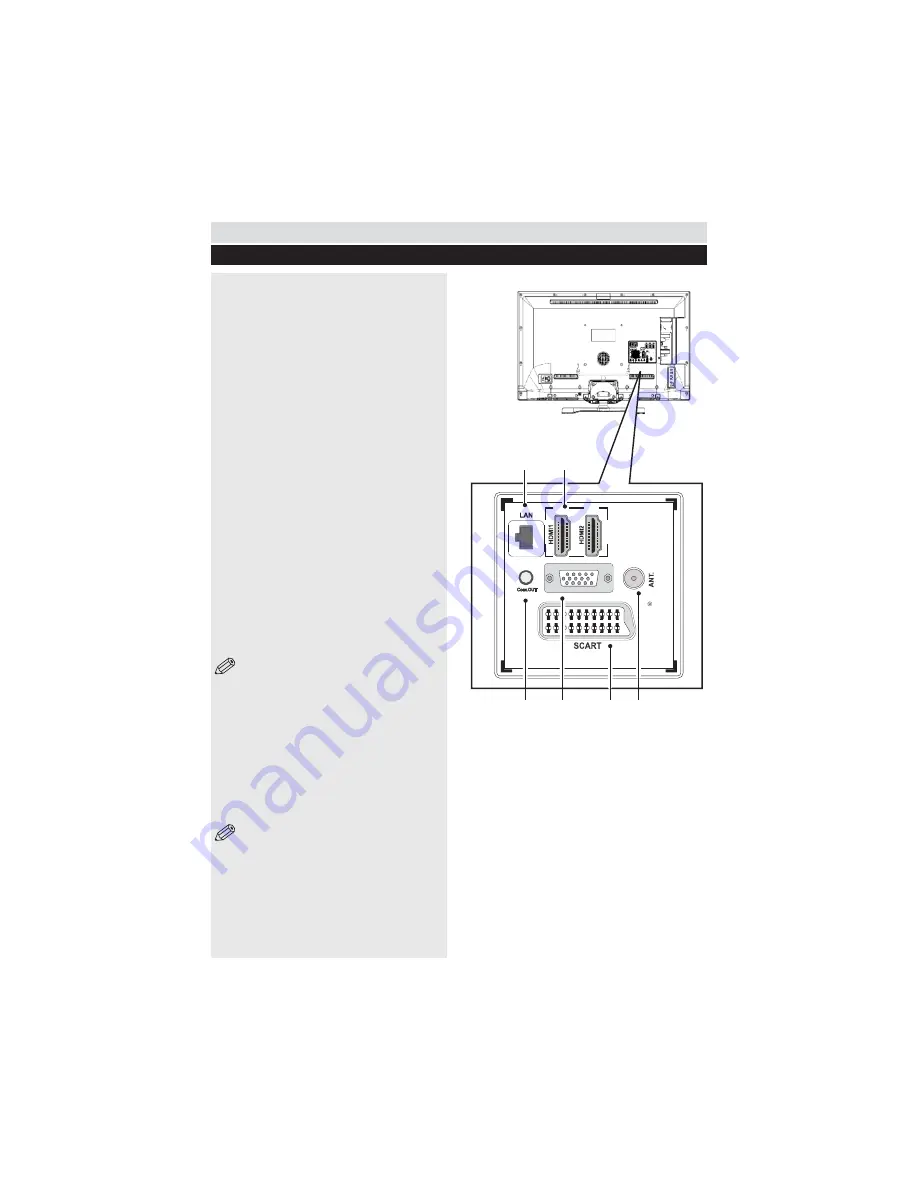
Back connections explained
VGA
SPDIF
2
4
1
3
5
6
16
1. Ethernet (LAN) Input
2. HDMI Input
Connects a device that has an HDMI socket.
The TV can display High Definition pictures
Q W W ##
Receiver or DVD Player. These devices must be
connected via the HDMI sockets or Component
Socket. No sound connection is needed for an
HDMI to HDMI connection.
3. S/PDIF Out
Outputs audio signals of the currently watched
source. Use an SPDIF audio cable to trasfer audio
signals to a device that has S/PDIF input.
4. PC Input (VGA)
Connects a personal computer to the TV. Connect
the PC cable between the PC INPUT on the TV and
the PC output on the PC. You can use the PC input
to allow YPbPr signal connection with a device that
has component output. Connect the YPbPr to PC
cable between the PC INPUT on the TV and the
component video outputs of the device.
5. SCART socket
Inputs or outputs for external devices. Connect
the SCART cable between the SCART socket on
the TV and the SCART socket on the external
device (decoder, VCR or DVD player).
NOTE
: If an external device is connected
via the SCART sockets, the TV will automatically
switch to AV mode. When receiving DTV
channels (Mpeg4 H.264) or while in Media
Browser mode, output will not be available via
the scart sockets.
6. RF Input (ANT.)
Connects to aerial (antenna) or cable TV. If you
use a decoder or a media recorder, you should
connect the aerial cable through the device to the
TV with an appropriate aerial cable.
NOTE
: When using the wall mounting kit
(optional), we recommend that you plug all your cables
into the back of the TV before mounting on the wall.
Summary of Contents for ELED42240FHDCNTD3D
Page 69: ...50234842 ...


