background image


 12 


2014  RDF  60, 72 

Mower Operation


The safe operation of this mower is the responsibility of the operator. 

The operator should be 

familiar with the machine, tractor and all safety practices before starting operation. This mower is 
designed for lawn and grass mowing. It is not designed for rough conditions or heavy weed mowing. 
The mower is equipped with suction type blades, which are best suited for lawn mowing. 

 
Always operate tractor at 540RPM. 

 
This chapter provides information for attaching mower to tractor and preparing it for field operation. 
Review this data prior to tractor hookup and operation. 


Tractor preparation 

 
Do not install mower on a tractor over 40 horsepower. 
 
WARNING!  

Do not operate tractor with less than 20% of it

’s gross unballasted mass on the front 

    wheels with the mower in the transport position. 


Wheel treads 

 
Tractor wheel tread spacing should be increased when working on inclines or rough ground to reduce 
the possibility of tipping. 

 
Stabilizer bars and sway blocks 

 
Use stabilizer bars or sway blocks to prevent side sway of the mower. 

 
Drawbar 

 
Shorten or remove the tractor drawbar so it will not interfere with the up and down movement of the 
mower. 

 
WARNING!  

Do not get between tractor and mower when the engine is running. 


Attaching the mower to tractor (lift type only) 

 
This mower is designed for tractors with 540 RPM and category I hitch. Back the tractor up to the 
mower so that the lower draft arms are in alignment with the mower lift pins. Stop the engine, lock the 
brakes or place the tractor in park. Connect the tractor and stabilizer bars to the lower lift pins. Adjust 


Summary of Contents for RDF 48

Page 1: ...derstand these instructions before operating or maintaining the machine Failure to do so could result in personal injury or even death to you or passersby Consult your Bush Whacker dealership if you do not understand the instructions in this manual or need additional information Hall Manufacturing Inc reserves the right to make changes at any time without notice or obligation Additional copies of ...

Page 2: ...stment 17 Starting and Stopping Cutter 17 Cutting Speeds 18 Cutting Tips 18 Detaching and Storing 19 Front Gauge Wheel Interference Check 20 Driveline Length Check Procedure 20 Adjusting Driveline Length 21 Troubleshooting 22 23 Mower Maintenance 24 30 Lubrication Information 24 Gearbox 25 Gauge Wheel Assemblies 25 Driveline Lubrication 26 Blade Spindle Lubrication 26 27 Blade Servicing 27 Blade S...

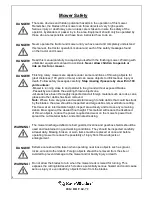
Page 3: ...ly inspected and all foreign material such as rocks cans glass and other debris has been removed Note Where there are grass and weeds tall enough to hide debris that could be struck by the blades the area should be inspected and large debris removed before cutting First mow at an intermediate height inspect area closely and remove any remaining debris Mow again at the desired final height This met...

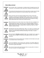
Page 4: ...ion is extremely hazardous Inspect the cutting area and remove any such objects before mowing Never allow the cutting blades to contact such items Be particularly careful while transporting the mower Turn curves or go up hills at a low speed and at a gradual steering angle Make certain that at least 20 of the tractor s weight is on the front wheels to maintain safe steerage Slow down on rough or u...

Page 5: ... close to the mower or tractor while in operation Usually children 15 16 years old who are mature and responsible can operate the mower with reasonable safety if they have read the operator s manual if they have been trained in safe operation of the equipment and if they are physically large and sufficiently strong to reach and operate controls with ease Never work under the mower deck the framewo...

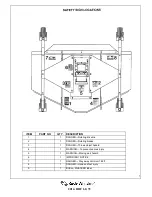
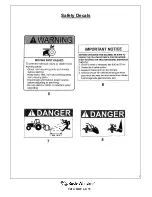
Page 6: ...Rotating driveline 2 1 DANGER Rotating blades 3 1 DANGER Thrown object hazard 4 1 WARNING To prevent serious injury 5 1 WARNING Moving part hazard 6 1 IMPORTANT NOTICE 7 1 DANGER Stay away minimum 160 ft 8 1 DANGER Hand and foot injury 9 1 BUSH WHACKER label ...

Page 7: ...8 2014 RDF 60 72 Safety Decals ...

Page 8: ...9 2014 RDF 60 72 Safety Decals ...

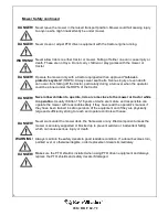
Page 9: ...ned with a signal word as shown below is intended to warn the owner operator of impending hazards and the degree of possible injury faced when operating this mower CAUTION The lowest level of safety message It warns the owner operator of possible minor injury Decals located on the mower with this signal word are black and yellow WARNING Serious injury or possible death These decals are black and o...

Page 10: ...ufacturer strongly recommends the use of chain guards or solid skirts for agricultural applications as well to reduce the risk of property damage serious bodily injury or even death from objects thrown or from contact with the cutting blades Front rear left and right are determined by the normal direction of travel the same as when driving an automobile Introduction continued ...

Page 11: ... tractor with less than 20 of it s gross unballasted mass on the front wheels with the mower in the transport position Wheel treads Tractor wheel tread spacing should be increased when working on inclines or rough ground to reduce the possibility of tipping Stabilizer bars and sway blocks Use stabilizer bars or sway blocks to prevent side sway of the mower Drawbar Shorten or remove the tractor dra...

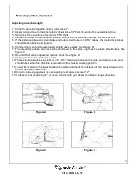
Page 12: ...amaging shock loads a mower can encounter and will cause damage to it and the driveline 1 Using the tractor raise the mower off the ground and place supports underneath of it so that it will not drift downwards while making adjustments or maintenance 2 While supporting the wheel and yoke assembly off the ground remove the snapper pin from the top of the gauge wheel spindle Position the supplied sp...

Page 13: ... a partial cut and or reversing the direction of travel may also produce a cleaner cut When people are passing by the area you are cutting stop the cutting until the area has been cleared Although the mower is shielded to prevent objects from being thrown by the blades no shielding device is 100 effective The mower operator has greater knowledge of the hazards created by the machine than people on...

Page 14: ...prevent contact from the ground and away from excessive moisture Always reinstall or lower into position the tractor PTO master shield This shield should always remain in place except when connecting or disconnecting the driveline Before operating or transporting the mower Always display the SMV slow moving vehicle symbol on the rear of the tractor that transports the mower The SMV symbol should b...

Page 15: ...ended position see assembly chapter 4 Move the tractor tires inward to obtain clearance or lower the mower until clearance exists 5 Set the 3 point quadrant stop so the mower cannot be raised beyond the set point See figure 5 Figure 5 Driveline length check procedure WARNING A loose shaft could slip off and result in personal injury or damage to the mower When attaching the driveline yoke to the t...

Page 16: ... figure B 7 The metal drive tubes also have to be shortened in the same length as the plastic shield tubes See figure C 8 Round off all sharp edges and remove burrs See figure D 9 Apply grease to the metal drive tubes 10 There should always be a minimum of 1 9 16 clearance between the male and female drive and shield tubes when the driveline is operated in its shortest working position 11 Lower th...

Page 17: ...too coarse Slow tractor s ground speed but mower unevenly or maintain 540 RPM PTO speed bunches along a swath Raise the mower for the first pass and lower to the desired cutting height for the second and cut at 90 degrees to the first pass Raise the rear of mower high enough to allow the grass to discharge but not too high for streaking to occur Belt slipping Tighten belt or replace with a genuine...

Page 18: ...uthorized dealer Damaged belt Replace it with genuine BUSHWHACKER belt Foreign object in sheave groove Inspect all sheave grooves for rust paint or other foreign material Remove these if present Worn sheave groove Replace with genuine BUSHWHACKER sheave Damaged belt Rollover high shock loads or Replace it with genuine installation damage BUSHWHACKER belt Belt breakage High shock loads Avoid abusiv...

Page 19: ...ages show the location of all the lubrication fittings Use an SAE multi purpose lithium type grease for all the locations shown on figure 7 Be sure to clean the grease fittings before applying any grease Daily lubrication of the driveline U joints is necessary Failure to maintain proper lubrication will result in premature wear and damage to the U joints gearbox and or driveline Figure 7 Lubricati...

Page 20: ...ded until it runs out of the test plug hole The filler plug hole and test plug hole are both located on the back of side of the gearbox Figure 8 Note It is recommended that the test plug be removed after every 8 10 hours of operation and oil added to the proper fill level if required Do not overfill the gearbox with oil This will result in pressure build up inside the unit which can cause the oil ...

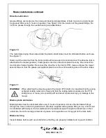
Page 21: ... that the grease just applied spreads over the entire working area of the drive tubes Figure 11 WARNING When attaching the driveline yoke to the tractor PTO shaft it is important that the spring activated locking collar turns freely and that the locking balls are seated on the PTO shaft groove A loose yoke could slip off and result in personal injury or damage to the mower Blade spindle lubricatio...

Page 22: ... razor edge but leave a 1 32 blunt edge Never sharpen the back side of the blades Figure 12 WARNING Avoid personal injury Always support or block the mower when servicing the blades carrier or any other component on the underside of the deck Blade removal Hold the end of the blade using heavy leather gloves and remove the Nut 1 Blade Installation Install Blade 3 Washer 2 on the Spindle shaft 4 Tig...

Page 23: ...box slide plate Reinstall belt shields and shield fasteners Figure 14 Drive belt removal and installation Shut off mower and tractor Remove drive belt shield fasteners and belt shields Loosen gearbox slide plate bolts and gearbox adjustment bolt See figure 14 Slide gearbox to its forward most position Slide belts under the gearbox sheave Item 7 and over the center spindle sheave Item 8 Make sure t...

Page 24: ...ration for the next season We suggest the following storage procedures 1 Thoroughly clean the mower 2 Lubricate the mower as recommended in the maintenance section of this manual 3 Tighten all bolts and pins to the recommended torque 4 Check the mower for worn or damaged parts and replace any that shows wear or damage 5 Store the mower in a clean dry place with the deck resting on blocks 6 Use spr...

Page 25: ...26 2014 RDF 60 72 ...

Page 26: ...esult in serious injury or death For questions regarding parts please contact BUSHWHACKER North Little Rock Arkansas tel 1 501 945 7550 BUSHWHACKER reserves the right to substitute parts where applicable Note Please make sure that your mower always has clearly legible safety decals as described in the mower safety chapter When ordering replacement decals refer to the safety decals part numbers des...

Page 27: ...28 2014 RDF 60 72 RDF 60 General mower assembly ...

Page 28: ...PACER 45 5298 4 SPACER 13 5269 2 JOINT PLATE 46 5299 12 BOLT 14 5255 26 FLAT WASHER 47 5300 4 BOLT 15 5244 26 LOCK WASHER 48 2693 11 BOLT 16 5270 26 NUT 49 5301 3 LOCK NUT 17 5322 1 DOUBLE PULLEY 50 5302 6 COTTER PIN 18 5272 3 LOCK NUT 51 5303 3 PIN 19 5323 2 SINGLE PULLEY 52 5304 1 MAIN DECK 20 5324 2 V BELT 53 5327 1 BACK PLATE 21 5275 1 PULLEY 54 5306 24 CHAIN 22 5276 1 SUPPORT 55 5307 2 LOCK N...

Page 29: ...30 2014 RDF 60 72 RDF 72 General mower assembly ...

Page 30: ...PACER 45 5298 4 SPACER 13 5269 2 JOINT PLATE 46 5299 12 BOLT 14 5255 26 FLAT WASHER 47 5300 4 BOLT 15 5244 26 LOCK WASHER 48 2693 11 BOLT 16 5270 26 NUT 49 5301 3 LOCK NUT 17 5271 1 DOUBLE PULLEY 50 5302 6 COTTER PIN 18 5272 3 LOCK NUT 51 5303 3 PIN 19 5273 2 SINGLE PULLEY 52 5304 1 MAIN DECK 20 5274 2 V BELT 53 5305 1 BACK PLATE 21 5275 1 PULLEY 54 5306 35 CHAIN 22 5276 1 SUPPORT 55 5307 2 LOCK N...

Page 31: ...32 2014 RDF 60 72 Notes ...

Page 32: ...or if the equipment shall have been operated subsequent to its involvement in an accident or breakdown un less the Owner furnishes reasonable evidence that such repair alteration modification or operation subsequent to its involvement in an accident or breakdown was not a cause of the defect The Owner does not return at Owner expense the defective accessory equipment component or machine to or not...

Page 33: ...NTY CLAIMS PROCEDURE Warranty claims must be delivered to Hall Manufacturing within thirty 30 days after the warranty service work was performed Hall Manufacturing will approved or deny claim within thirty 30 days of receiving a claim Hall Manufacturing will issue credit for all genuine Bush Whacker parts or components as well as all approved Dealership employee labor time at a rate of 30 00 per h...

Page 34: ...urchaser _____________________________ Address __________________ City_____________________ State ________ Product ___________________ Model ___________ Serial _____________ Dealer Address City State Signature of Original Buyer Signature of Dealer or Dealer s Agent Please include a copy of the original bill of sale ...

Page 35: ......

Page 36: ...ee to the protected area provided by the ROPS Required of the operator 1 Securely fasten seatbelt if the tractor has a ROPS 2 Where possible avoid operating the tractor near ditches embankments and holes 3 Reduce the tractor s ground speed when turning crossing slopes and on rough slick or muddy surfaces 4 Stay off slopes that are too steep for safe operation 5 Watch where you are going specially ...

Page 37: ......

Reviews: