


26
27
IT
ES
NL
FR
EN
DE
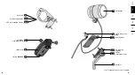
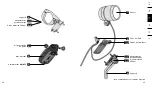
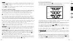
Detail A
6.2. Electrical connection of the LEVAL to a separate power source
(e.g. for connection to bicycles where the lighting system is operated via a dynamo, to another power
outlet on the e-bike drive, or to a power bank).
If the LEVAL is connected via a separate power source which is switched on, it can also be active
when the lighting system is switched off. The specifications mentioned under „5. LEVAL - Technical
specification“ must be met by the power source. This must be ensured before putting the LEVAL into
operation.
Since the LEVAL is not connected together with the headlight but is powered separately, the head-
light cable is not plugged into the LEVAL but connected directly to the power source.
For the power supply of the LEVAL, only the connecting cable of the power source has to be connec-
ted to the LEVAL.
The connection is under the locking plate
4.2
and is realised by means of the cable connector inclu-
ded in the scope of supply. Proceed as follows: Connect the cable with the cable connector
6
.
First prepare the connecting cable of the power source to be able to insert it into the LEVAL using
the cable connector/plug for connection.
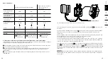
Remove the last 2 cm of the cable sheath from the connecting cable. Now strip off 5 mm of insula-
tion from each of the exposed cable strands (1x power and 1x earth).
To open the cable connector/plug, loosen the respective screw.
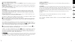
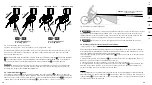
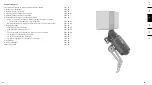
Fig.: Headlight and the LEVAL connected to two separate power sources (a & b)
Then insert both the power wire of the headlight and the power source into the correct opening
of the cable plug/connector (ensure correct polarity!), and repeat the same with the ground. Now
close the cable connector again with the screw.
After that, open the locking plate
4.2
by loosening the four black screws that hold the locking
plate
4.2
to the LEVAL. Then plug in the cable connector
6
as shown on the housing (detail A).
Finally, close the LEVAL again with the locking plate
4.2
To protect the LEVAL from penetrating
dirt and moisture, carefully tighten the screws in a way to ensure they cannot come loose all by
themselves.
NOTICE
When shortening cables, always make sure that the remaining cable lengths are suffi-
cient to make sure the LEVAL can move freely and is not restricted in its freedom of movement
by the cables.
7. LEVAL assembly
Before assembly, make sure to check there is sufficient power available to operate the LEVAL (see
„6. Power Supply / LEVAL connection“).
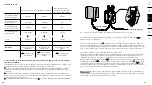
7.1. General assembly
Securely attach the LEVAL to the bicycle between the headlight
1
and the bracket
2
so that the
headlight cannot adjust itself or change its position on the bicycle when the LEVAL is switched off
(switch
3
to „OFF“).
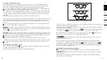
Using the positioning adapter
4.1
, the LEVAL can be mounted in four different positions to ensure
it is located as compact as possible and at an optimal angle of approx. 45° between the headlight
1
and the bracket
2
(see drawing).
Select the optimum mounting position for your bicycle
The locking plate
4.2
of the LEVAL must always remain on the underside of the LEVAL, while
the positioning adapter
4.1
can be attached on the top or underside of the LEVAL (see drawing),
depending on the mounting option. For the suspended mounting options (LEVAL mounted under-
neath the bracket), the LEVAL must therefore be converted as follows: Remove the positioning
adapter
4.1
from the locking plate
4.2
by loosening the black screws in the LEVAL housing and
attach the positioning adapter on top of the LEVAL housing using the black screws. Tighten the
screws in a way to ensure they cannot come loose all by themselves.
NOTICE
The swivel arm
5
must always be on the r.h. side in the cycling direction.
power source b
(e.g. power bank)
power source a
(e.g. dynamo)
Summary of Contents for LEVAL 365
Page 50: ...98 99 ...